Each planet in “from space” view has two sides: “day” – illuminated by Sun, and the opposite – “night”, with no Sun lighting.
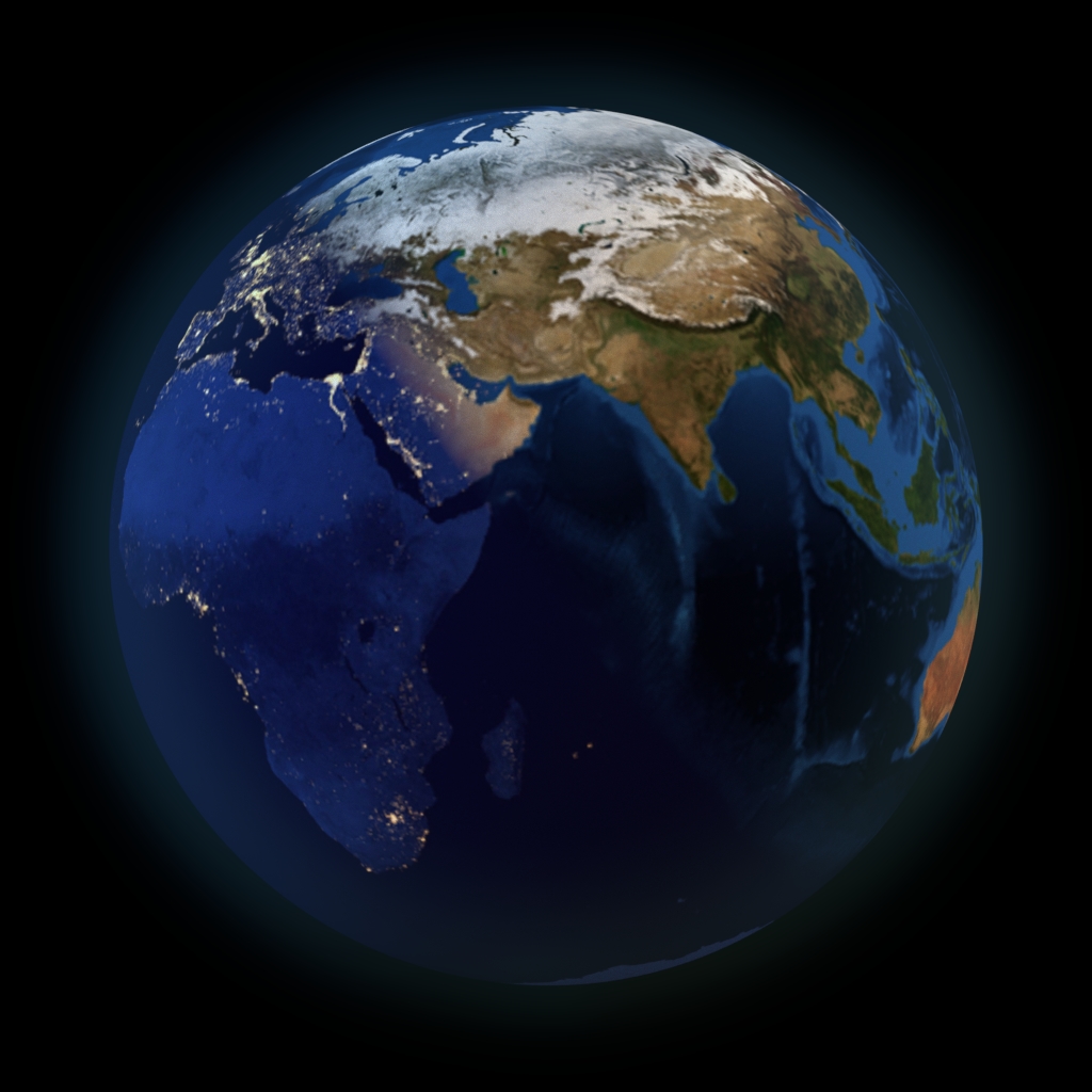
While modeling a scene with planet, it is not difficult to achieve this effect by lighting setup. Leave only one lighting source in scene and place it in the right place. However, the result is not so good as real space photographs. To achieve a greater similarity, the proper texture with a darkened face and bright lights – night lights of big cities, mast be mapped to the “night” side of modelling planet.
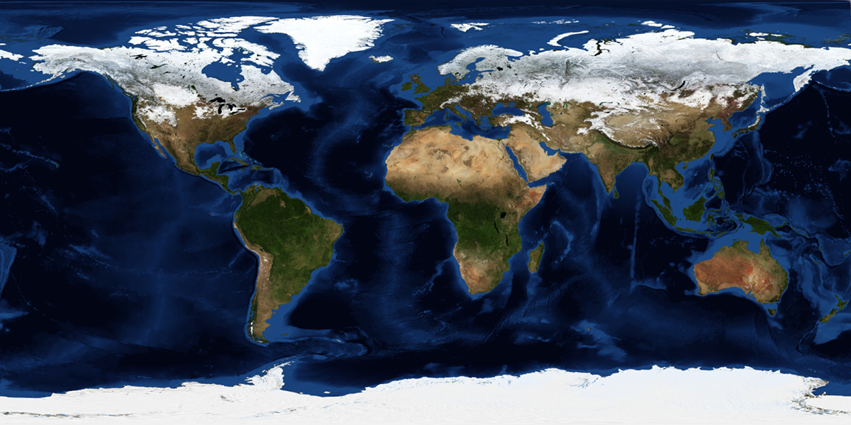
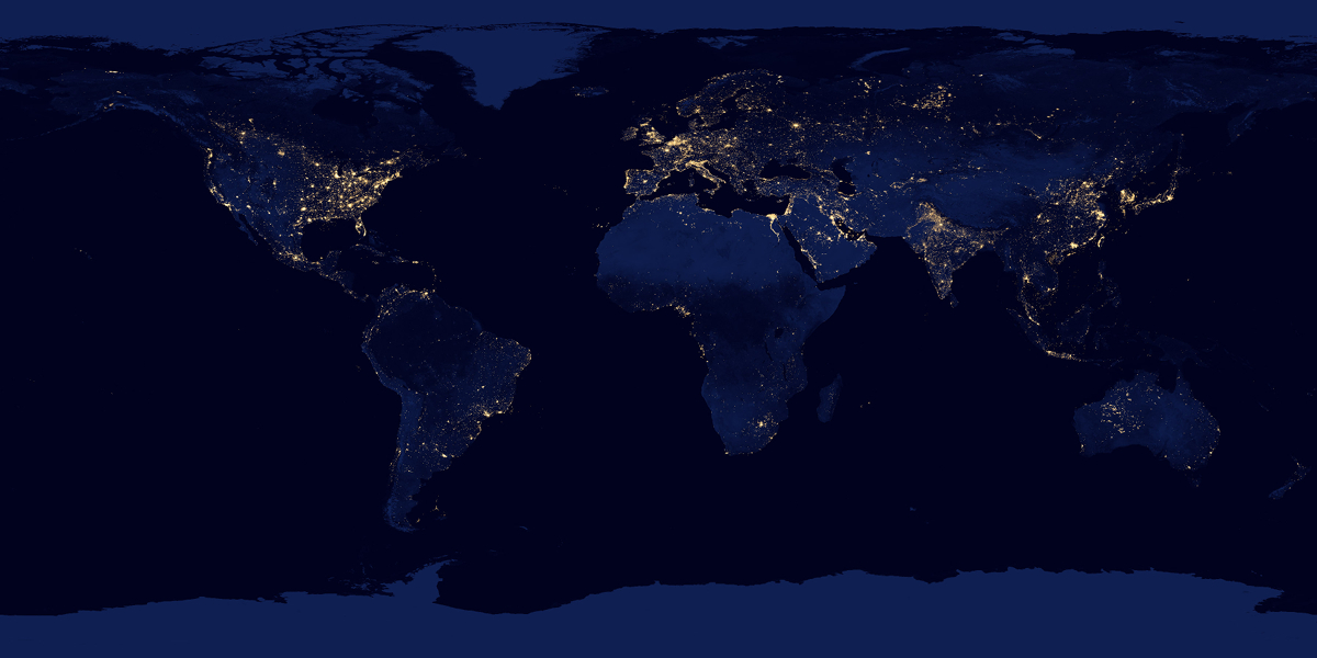
Prepare two textures: “day” and “night” – for each side of our modelling planet:
Create Earth:
- Create a sphere
- shift+a – Mesh – UV Sphere
- In the T-bar
- Transform
- set Shading to Smooth
- Transform
- Add modifier Subdivision Surface
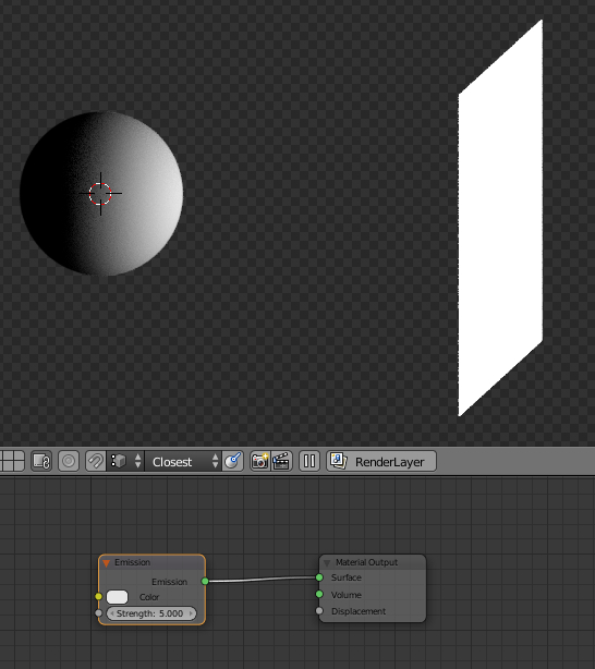
Create a light source – the “Sun”:
- Create plane and refer its flat side to sphere-Earth:
- shift+a – Mesh – Plane
- Move and scale it a bit
- g – x – 5 – enter
- Light plane coordinates after moving are X = 5, Y = 0, Z = 0. They will be needed to us in the future, in customization nodes tree.
- s – 2 – enter
- Bind it:
- Select plane
- Select shpere with pressed shift
- ctrl+t – Track To Constrait
- Rotate plane always looking to sphere by the side
- Select plane
- Enter Edit mode (tab)
- r – y – 90 – enter
- Off Edit mode (tab)
- Create light source material for plane
- In Node Editor
- Create new material for the plane
- Replace Diffuse node with Emission node
- Select Diffuse node
- shift+s – Shaider – Emission
- Strength = 5
- In Node Editor
- g – x – 5 – enter
Correctly map prepared texture to sphere-planet. Make a separate node branches for the “day” and “night” patterns:

It remains to properly combine created node branches by the terminator – line that separates the illuminated side of the planet from the darken side, to use “day” texture on the illuminated side of the Earth, and “night” – on the darken.
Unfortunately Blender has no input node parameter, to get luminance value at current shaider point. However, to solve this problem, we can use the fact that at any point of the spherical surface of our planet normal vector is known. Lets remember a bit of vector algebra and take a look at sphere cut. We may notice that the angle between the sphere surface normal vectors (blue) and the vectors of incoming to the sphere surface light (yellow) evenly changes from 0 to 90 degrees just like the sphere surface illunination changes.
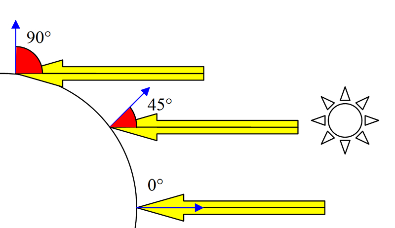
Lets admit the angle of 0 degrees for full illumination. Then any increasing the value of this angle corresponds to decreasing in surface luminance at current point. It remains to get this angle value and use it as mapping factor of “day” and “night” Earth textures.
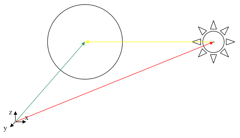
To get the desired angle we have normal vectors of the planet surface, but there is no vector of the incoming to the surface light. However, knowing the position of the light source, we can get the desired vector. There are two vectors: the first – from the point of origin to the location point of the light source (red) and the second – from the point of origin to the lication point of the sphere-planet (green). The required vector (yellow) will be the result of subtraction of these two vectors.
Transfer the resulting vector in nodes system:
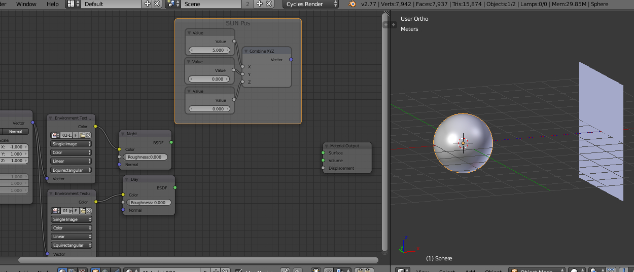
- In the Node Editor in Earth’s material create three value nodes – to define the light source position.
- shift + a – Input – Value
- shift + d – move
- shift + d – move
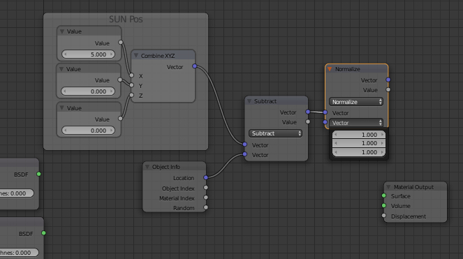
- Combine this three nodes to Vector
- shift+a – Converter – CombineXYZ
- Value nodes outputs connect to the node CombineXYZ input
- Set light source X-Y-Z coordinates to the Value nodes (values from st. 2.2.1.1.).
- Add Object Info node – to get our sphere-planet location
- shift+a – Input – Object Info
To get incoming light vector it is necessary to subtract location vector of the planet from the location vector of the “Sun”.
- Add vector operations node:
- shift+a – Converter – Vector Math
- Choose subtraction: Subtract
- Connect Vector output (CombineXYZ) to the upper Vector input (Vector Math)
- Connect Location output (Object Info) with the lower Vector input (Vector Math)
- shift+a – Converter – Vector Math
- Normalize the resulting vector – make its length equal to 1.
- Add Vector Math node
- shift+a – Converter – Vector Math
- Choose a normalization operation: Normalize
- The upper Vector input (Vector Math) connect with Vector output (Subtract)
- Lower input Vector values (Vector Math) set to 1,1,1
- shift+a – Converter – Vector Math
- Add Vector Math node
The result is a normalized incoming light vector.
Now we need to get the angle between this vector and the normal vectors of the sphere surface. The dot product of two vectors – value that characterizes the ratio of the lengths of two vectors and angle between them. The normal vectors of sphere surface are initially normalized and we normalized calculated incoming light vector manually so the lengths of all the vectors are equal to 1, and the ratio of their lengths is equal to 1 too. The scalar product of vectors in this case depends only on the angle between vectors and is equal to the cosine of this angle. Cosine values varies from 0 to 1, which is more easy to node system than the angular values.
Make the scalar product of the desired angle in node tree:
- Add node, which will give us the value of the normal vector at the current shaider point:
- shift+a – Input – Geometry
- Add vector operations node:
- shift+a – Converter – Vector Math
- Set the operation of the scalar product (Dot Product)
- Connect the upper Vector input (Dot Product) with Vector output (Normalize)
- Connect the lower Vector input (Dot Product) wit Normal output (Geometry)

The result is a value representing the angle between the planet’s surface normals and incoming to the planet’s surface light. Use this value to mix two prepared textures of the day and the night.
- Add Mix Shader node
- shift+a – Shaider – Mix Shaider
- Connect Shaider output (Mix Shaide) with Surface input (Material Output)
- Connect the upper Shaider input (Mix Shaider) with BSDF output (Diffuse) node with the “daytime” texture
- Connect the lower Shaider input (Mix Shaider) with BSDF output (Diffuse) node with the “night” texture
- Connect Factor input (Mix Shaider) with Value output (Dot Product)
- shift+a – Shaider – Mix Shaider
Now the “daily” texture is shown on the illuminated side of the planet , and “night” texture – on its dark side. However, the angle between planet surface normals and incoming light, depending on which we put a texture mixture factor, changes uniformly from the brightest point of the surface to the darkest, so textures start to mix almost immediately, the terminator of the planet is too blurred, and the most part of the “day” side of the planet overlaps with “night” texture. Make simple correction and add Color Ramp node to our node tree:
- Add Color Ramp node
- shift+a – Converter – Color Ramp
- insert it into connection between the Vector output (Dot Product) and Factor input (Mix Shaider)
- Move right (white) Color Ramp node slider to the left, to correct terminator borders.
Now there is clear “day” texture on the illuminated side of our planet, “night” on the dark side, and throug the terminator we can see a rapid transition from one state to another.
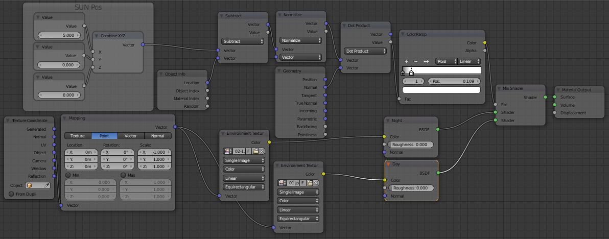
Finished node tree looks like this:
Configure final scene and send it to render.
While configurating your scene, remember – if you move the lighting source, also enter new coordinates of the light source to the Earth node tree to separate the “day” and the “night” correctly.
Textures of the Earth’s day surface and Earth’s night surface taken from nasa.gov site for educational purposes only.