Geometry Nodes

Getting the angle between edges using Blender Geometry Nodes if several edges come out of a vertex

In the “Calculating the angle between edges using Blender Geometry Nodes” post, I was asked what to do in a more general case, when several edges come out of one vertex of the mesh? This problem can also be solved using Geometry Nodes, but the approach to the solution here is slightly different.

Calculating the angle between edges using Blender Geometry Nodes

When procedural modeling in Blender using Geometry Nodes, we often use various parameters of mesh geometry, such as the position of vertices in space, the length of edges, direction of the normals, etc. Also, quite often we need to know the angle between two adjacent mesh edges. Getting it using GN and mathematics is not difficult.

Passing values ​​from Blender Geometry Nodes to other scene objects

Using drivers, we can pass values ​​to the Blender Geometry Nodes tree that cannot be obtained from nodes, for example, the total number of frames in a project animation. However, there are cases when a value needs to be passed from Geometry Nodes to some property of an object not related to GN. In this case, drivers can also help us.

Working with inputs and outputs for the Capture Attribute Node in Blender Geometry Nodes

Starting with Blender 4.2, the Capture Attribute node has changed in functionality. If earlier this node always had only one “Value” input and only one “Attribute” output, intended for recording attributes, in addition to the standard geometry socket, then starting with version 4.2, the number of inputs/outputs for recording attributes has been made dynamic.

Placing Max/Min socket controls of geometry node on the user panel

In order to display the value of a socket on the Geometry Nodes modifier panel in Blender, we simply need to create a link and connect the desired socket of the desired node with an empty socket on the Group Input node. After this, a field appears in the modifier panel in which we can change the value of the desired socket. We can then place this field on the user panel by accessing it as a dynamic property.

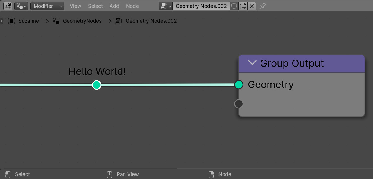
Labels for Reroute nodes in Blender Geometry Nodes

Did you know that you can set your own text labels for Reroute nodes in Blender Geometry Nodes? Since Reroute nodes are most often used to simplify and improve the readability of node trees in Geometry Nodes, marking such nodes with a label with a short informational inscription can be very convenient – you will not need to remember or scroll through the tree of nodes every time to find out where this Reroute data comes from.