There is one moment in node tree, created to separate the sides of the planet model by “day” and “night” – when the position of light source changes its new coordinates every time needs to re-specify manually in Value nodes. It is very inconvenient while setting the scene. To eliminate this fault Blender “drivers” system can be used.
Lets make a simple scene showing the separation of the planet sides. Create a planet (sphere). The light source (plane) locate at 5,0,0. Create a material with “day” and “night” separation, append it to planet.
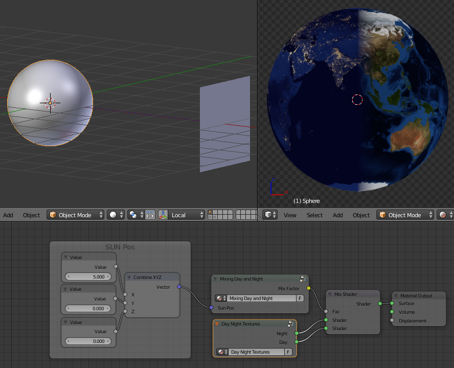
Simplify nodes tree packing what we do not need during setup into the groups.
- Select the desired nodes
- ctrl+G

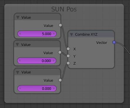
There are only Value nodes with the coordinates of the light source outside groups. We will setup drivers to them.
Drivers – a Blender mechanism that uses properties, numbers, transformations, and scripts, to control the values of properties. In simple – drivers proceed dependences some object properties from properties of other objects. In this case we need to associate values from Value nodes in planet material with lighting plane coordinates.
To install driver to the X lighting source coordinate Value node:
- Click the right mouse button on the numerical value of Value node for X coordinate
- Select Add Driver

The value will painted in purple.
- Open the Graph Editor
- In its menu set Mode to Drivers
If node with driver is selected, the Graph Editor displays the name and path of the controlled value, curve and Drivers tab in the N-bar.
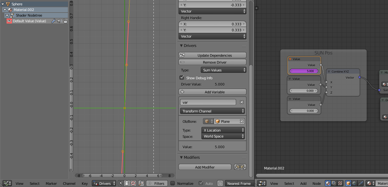
Pay attention to Drivers tab. First we need to configure driver type, regulated with Type parameter. Driver type is a formula that calculates driver output value. There are several variants:
- Maximum Value
- Minimum Value
- Scripted Expression – output value calculates by the expression on the scripting language
- Sum Values
- Average Values
These formulas, except Scripted Expression, are needed in order to handle multiple input values by driver. For example, if single object’s position depends on the positions of several other objects. Through a driver that handles multiple input location values, one result can be calculated. A Scripted Expression type you can set to get the output values from scripting language Pithon – this type is used, if other types are not enough.
In our case, we have one input value – X coordinate of the light source. Therefore, we can choose any type of driver, except Scripted Expression. For example – Sum Values. The sum of single number always equal to the same number.
- In Graph Editor
- In N-panel
- Drivers tab
- set Type to Sum Values
- Drivers tab
- In N-panel
Next, pay attention to created by default variable named “var”. This variable is the actual input value, which handles by driver. It also has a type:
- Distance – the distance between two objects
- Rotation Difference – the difference between the rotation angles of two objects
- Transform Channel – location data of the object
- Single Property – value of any object parameter, defined by the scripting language
All types, except Single Property, are used to obtain values that required more often. Like driver type, Single Property can be used to get any value of the object using the Pithon language. In our case we need to get the X coordinate of the light source. Therefore, we select the Transform Channel type.
In the Object/Bone field specify the object – the source of the input value. In our case – a light plane. It is necessary to specify the desired type of coordinate:
- In Graph Editor
- In N-panel
- Drivers tab
- “var” variable
- Set Type to Transform Channel
- In the Object/Bone field specify the light plane
- Set Type to X Location
- click the Update Dependencies – upgrade the relationship, ie, apply the specified values
- “var” variable
- Drivers tab
- In N-panel
Driver that connects the X coordinate of the light source and the Value node for this coordinate in the planet node tree is created and configured. Now if we try to move the light plane by its X coordinate from different sides of the planet, we can see that “day” and “night” textures changes their places.
In the same way we need to create and configure the two other drivers for the two remaining coordinates.
- Click the right mouse button on the numerical value of Value node for Y coordinate
- Add Driver
- Select node
- In Graph Editor
- In Drivers tab
- set Type to Sum Values
- For “var” variable
- set Type to Transform Channel
- In the Object/Bone field specify the light plane
- set Type to Y Location
- Press the Update Dependencies
- In Drivers tab
- In Graph Editor
- Click the right mouse button on the numerical value of Value node for Z coordinate
- Add Driver
- Select node
- In Graph Editor
- In Drivers tab
- set Type to Sum Values
- For “var” variable
- set Type to Transform Channel
- In the Object/Bone field specify the light plane
- set Type to Z Location
- Press the Update Dependencies
- In Drivers tab
- In Graph Editor
All three drivers for three coordinates of the light source are configured. Now we can move the light plane to any place – “day” and “night” textures of the planet always will be mapped correctly.