By Andrew M.
“Many letters about the simple”
I need a frame. No, two frames: one larger, the other smaller, but made from one profile. I drew a rectangle, set the desired dimensions, duplicated, set other sizes. I drew a separate profile. For a section to both rectangles I applied this profile. … why did I get different frames? And none matches the size of the profile? Ah, I forgot to apply the scale. Applied. The dimensions of the cross-section changed, became different, but again not equal to the profile. How to make them equal – read below!
Solving the problem of the discrepancy between the size of the track section and the profile applied to it
This problem occurs when the path for profiling is constructed in any way but then scaled to the desired size. In this case, it does not matter if its scale is 1 or not. If we apply the profile we need to it, then it will be different in size from the set … Why? We will see now.
To start, we will consider and understand how the cross-section of the path is built and what it depends on. For this:
– build a path, for example, a Bezier curve …
Here you need to make a footnote, the drawing of any detail should start in the TOP VIEW! Even if you created a Bezier curve in front view, Blender created it in top view! You can verify this by going to the edit mode -> top view and see that it is curved, and its normals are on the X plane. If you continue to edit it when viewed from the front, you will bend the normals and draw a geometrically even profile is hardly possible. To continue drawing in front view, after creating the first segment, in object mode, flip it along the X-axis 90 degrees and continue. We are distracted, we will return to our question.
– build a path, for example, with a Bezier curve and DO NOT SCALE (do not change its size);
– to make it clearer:
make it completely straight;
unfold in a top view end to us;
we tie its position to the marking;
call the “path”;
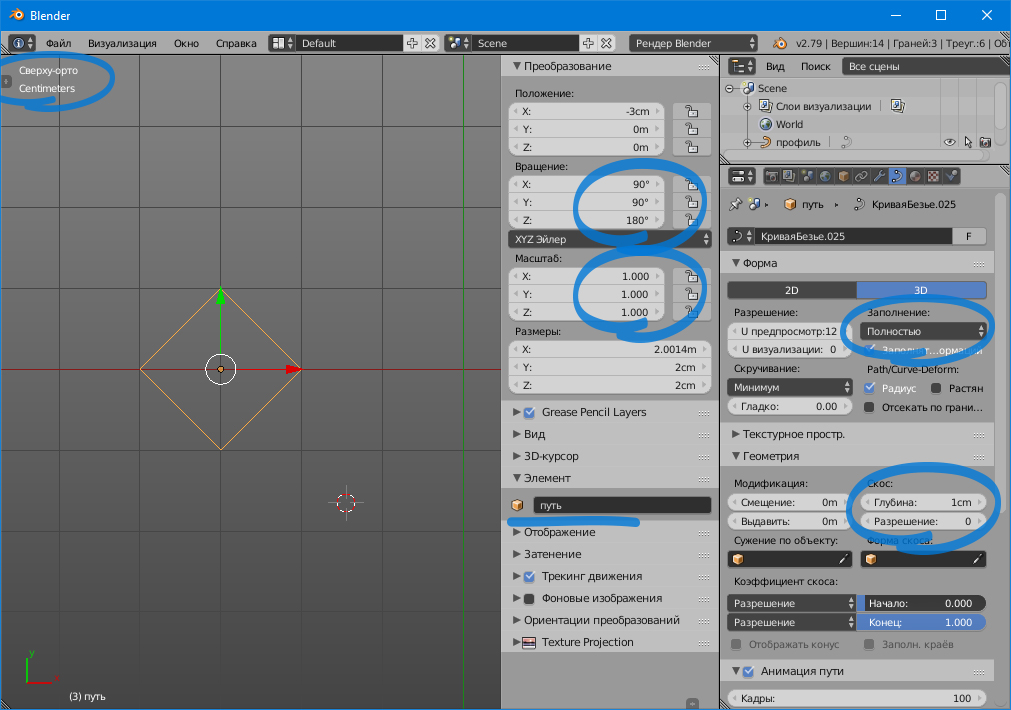
– go to the properties panel -> the data tab of the object: set the filling – completely, assign a bevel to it – say, 1 cm.
– we get close enough to see it and make sure that a volume equal to 1 cm appeared from the path in both directions.
Fine! But that is not the answer. We continue.
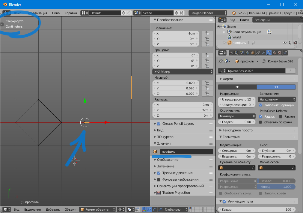
– draw alongside, also in a top view, a profile that will be a section of our path. For clarity, its size is 2×2 cm. We set the anchor point in the corner. Name it “profile”:
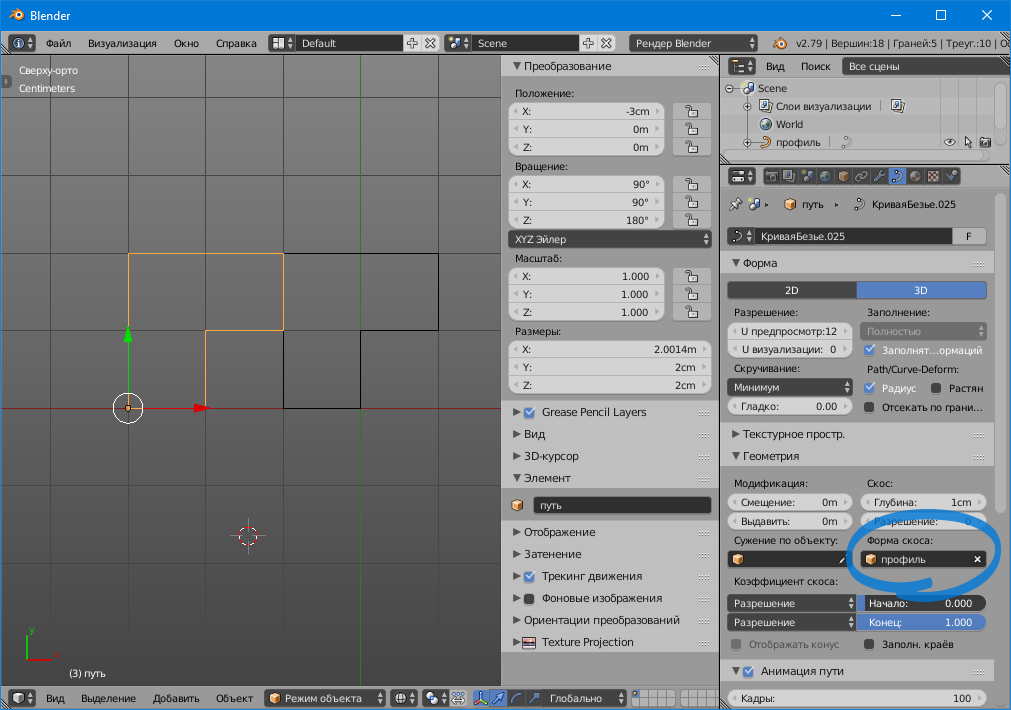
– in the properties of our “path” we prescribe this “profile”;
– we see that the cross-section of the path exactly matches the profile.
Great again, but not all!
– as usual for clarity, we remove the bevel shape along the path, set the bevel size to 0. The result is a bare straight line;
– increase it one and a half times. DO NOT set the scale to 1!
– duplicate it and reduce it by one and a half times from the initial one. DO NOT set the scale to 1!
It turned out two straight lines of different sizes.
– we put a bevel of 1 cm on both paths in turn.
– in the view from above, we get close enough to see them and make sure that from the paths in both directions a volume of NOT EQUAL 1 cm appeared!!!

In the larger path, it is more than 1 cm, in the smaller, respectively, smaller. And here you will say that the scale is not 1. Well, set the scale for each curve 1 (in object mode – ctr A -> scale) and …. the size of the bevel has not changed.
– check how the path will work out the shape of the bevel. For each path, we prescribe our profile in the shape of the bevel and see … it is the same as the bevel, differs in size from the drawn 2×2 profile in the larger and smaller direction.
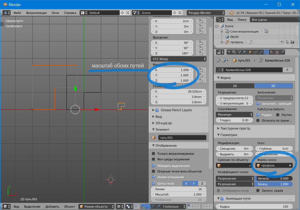
The scale of each curve is 1. And here the main catch is that the scale is not responsible for the ratio of the bevel to the path, but another function is responsible for this.
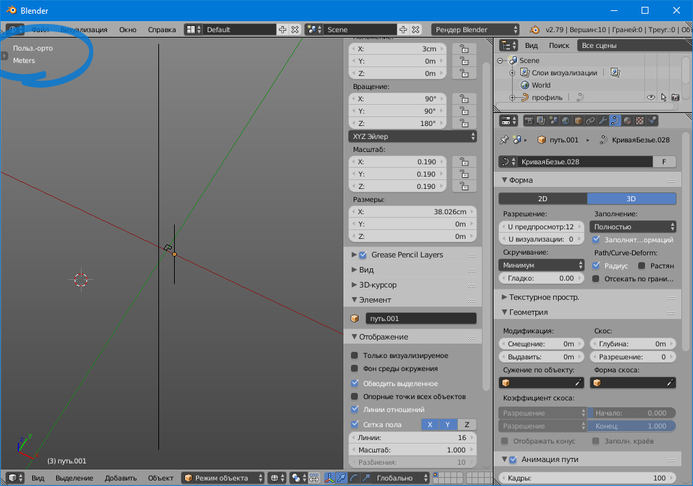
Take a greater path, leave our profile in the shape of a bevel. Check that the scale is set to 1. This is important. Select the path -> edit mode (tab) -> select all (A) -> in the N-panel (N) -> the “Transformation” tab. There we see the parameter “average radius”. After scaling and reducing the scale to 1, the value of this “average radius” is greater than 1 <- THIS IS A COOL!
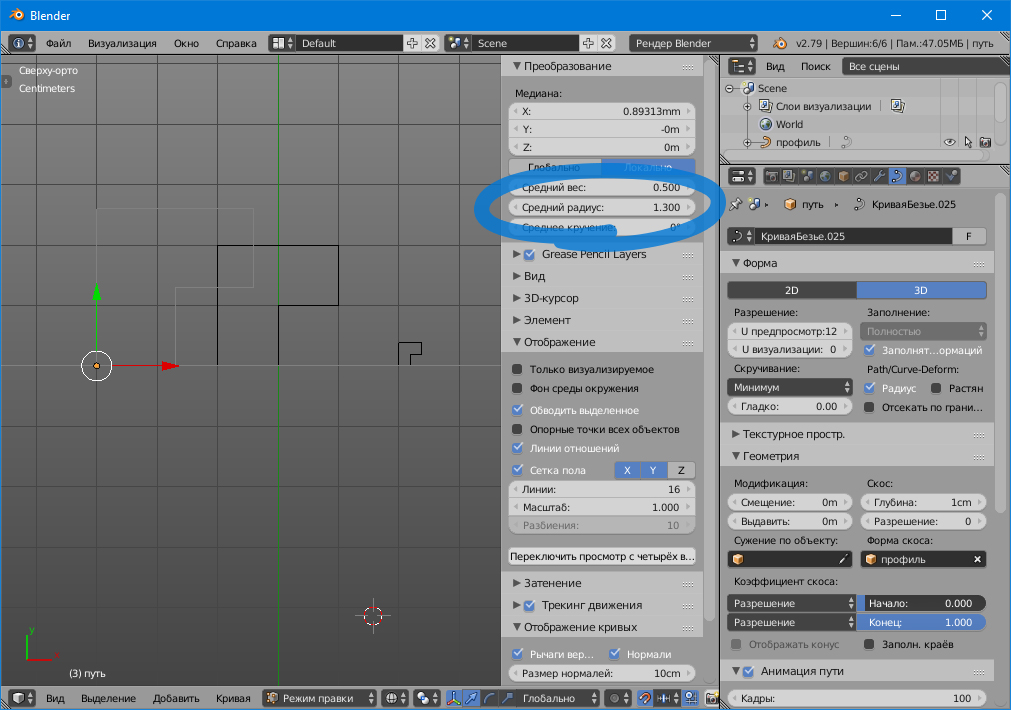
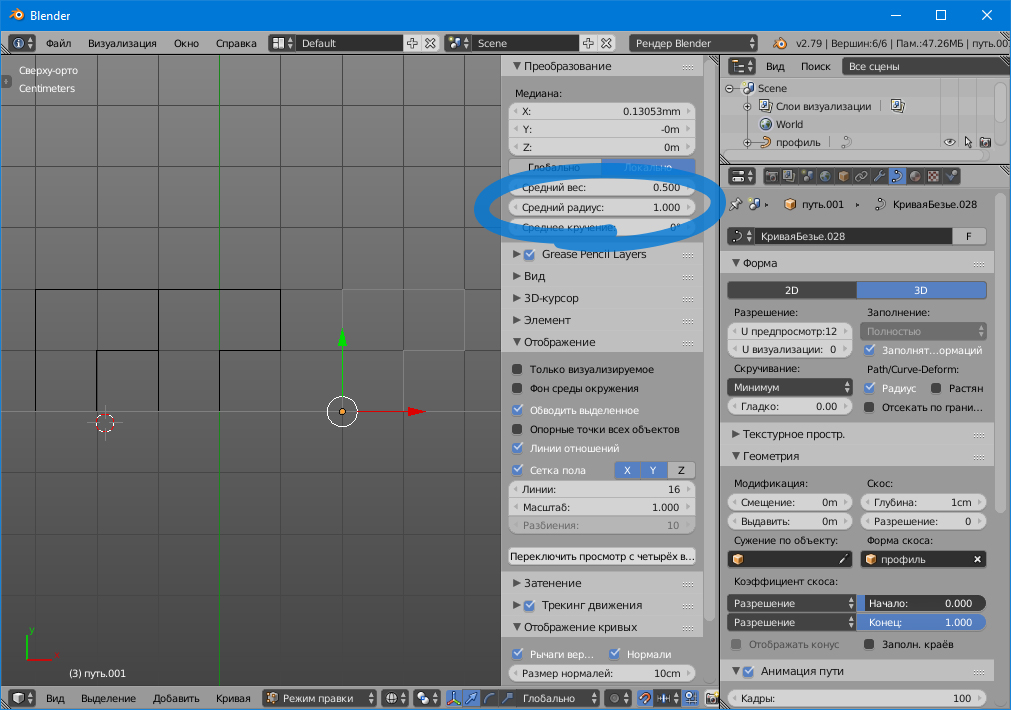
This is a parameter for the proportion of the section to the profile! We put 1 in this line and see that the section has become equal to the profile. Yes, you did it! By setting the value of the “average radius” = 0.5, we get a section exactly 2 times smaller, etc. So we can additionally influence the ratio of the section to the profile on different paths having one profile for this. And we can even change this attitude at different points of the path.
Now you can safely create at least one hundred frames of different sizes from one profile.
All the best!