With the coordinates of the UV, we can manipulate not only materials but also the geometry of the mesh itself. We can connect the UV coordinates with the mesh geometry using “Geometry Nodes” in Blender.
 Content on Patreon
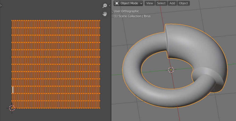
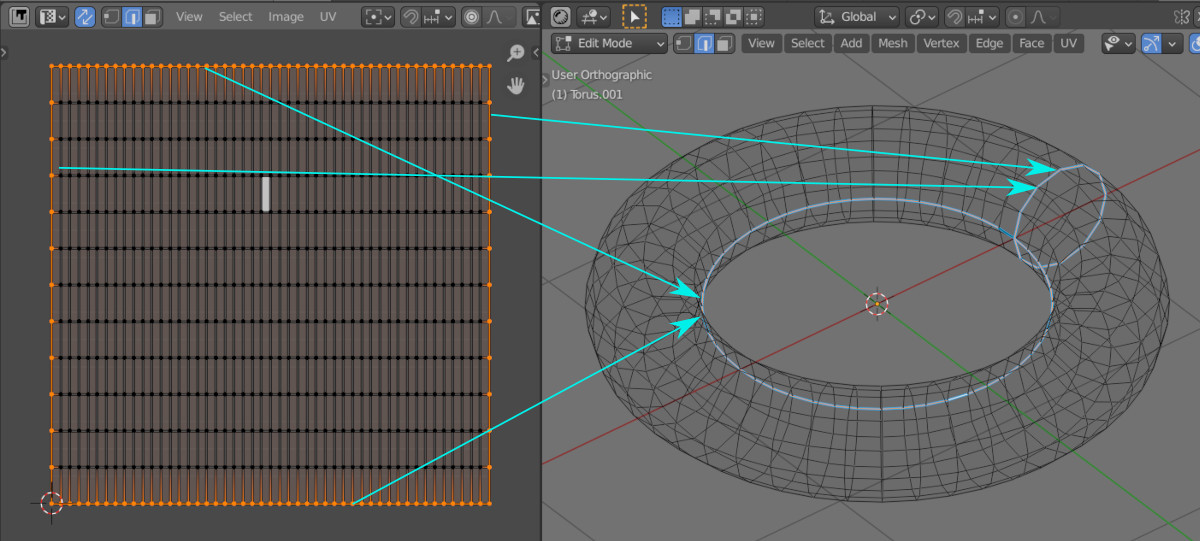
Let’s add a torus to the scene (shift+a – Mesh – Torus). The automatically generated UV for this mesh makes like with two seams: longitudinal – along the X-axis and transverse – along the Y-axis.
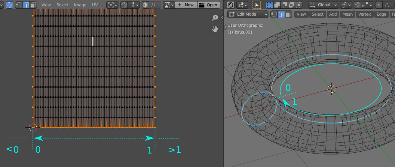
The UV coordinates are counted in the range from 0 to 1. The normalized coordinates of the mesh vertices are in the same range. For example, for the X-axis:
We can map the UV range to the mesh geometry with”Geometry Nodes”.
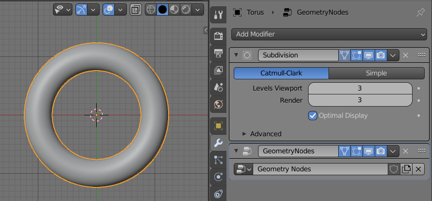
Let’s add two modifiers to our mesh: “Subdivision Surface” – to make the mesh subdivision denser and the geometry smoother, and “Geometry Nodes” – to enable the geometry nodes.
Open the “Geometry Nodes” editor in a separate window.
Add the “Attribute Separate XYZ” node to the node tree (shift+a – Attribute – Attribute Separate XYZ). In the “Vector” input, let’s specify the “UV Map” mesh attribute. This attribute allows us to access the UV map points coordinates. In the “Result X” field we will set the value “X”, and in the “Result Y” – “Y”. This will create two new mesh attributes named “X” and “Y” to which the node will translate the normalized UV coordinates separately along the X and Y axes.

To transfer UV coordinates to the mesh geometry, add an “Attribute Math” node and switch it to “Less Than” mode. For the input “A” specify the attribute “X”, and switch to the “Float” mode the input “B”. In the output let’s specify a new attribute named “selection”.
Now the value obtained from the “X” attribute is compared with the value from the “B” input. If it is less – 1 is transmitted to the “selection” output, if grater – 0.
Thus we mark the selected mesh points, the UV coordinates of which lie in the specified range.

Having the selected points, we can now change the geometry only for them. For example, let’s scale the specified part of the mesh.
Add three “Attribute Vector Math” nodes to the node tree (shift+a – Attribute – Attribute Vector Math):
- Switch the first one to the “Multiply” mode. In the first input attribute field specify “normal” – this is the normal of the current mesh point. In the second input field set the “selection” attribute – the attribute we have created to select the desired mesh points. Type “factor” in the output attribute field – the result of multiplying the normal by the point selection will be translated into this attribute. As a result, the value will be 1 for the selected points, and 0 for the unselected ones.
- Switch the second “Attribute Vector Math” node also to the “Multiply” mode. Set the “factor” attribute to the first input, and switch the second input to the “Vector” mode. At the output, again specify the “factor” attribute. This node allows us to regulate the scale value. We just multiply the value of the normal vector by the coefficient specified in the “Vector” input.
- Switch the third “Attribute Vector Math” to the “Add” mode. At the first input, set the “position” attribute – the position of the current vertex. In the second input, set the “factor” attribute – the value along the normal for this vertex At the output, specify again the “position” attribute. We add the vector of the vertex position with the vertex normal vector multiplied by a factor and assign the result to the vertex position.
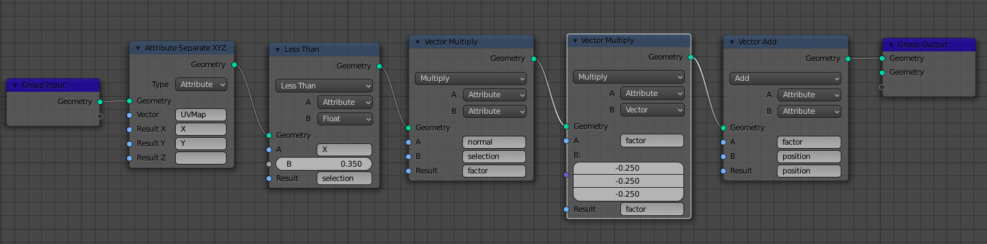
As a result, we get the displacement of vertices along the normal by the specified coefficient, and this is only for the selected points. For unselected points, the “factor” value is 0, so the result of the operation does not affect the mesh geometry.
By changing the value in the second input of the “Less Than” node, we can clearly see how the mesh geometry changes.