With Geometry Nodes in Blender, we can easily transform any object into its UV map.
 Content on Patreon
And it is not necessary to bake the coordinates transformation of its points into shape keys. With the Geometry Nodes, we can do this very simply.
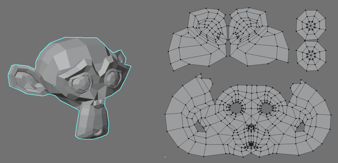
Let’s add an object to the scene, for example, Suzanne: shift + a – Mesh – Suzanne.
Add the Geometry Nodes modifier to the object.
Switch to the Geometry Nodes area and add a “Set Position” node to the main tree branch.
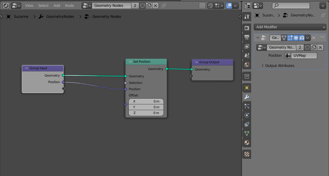
Extend the link from the “Position” input of the “Set Position” node to the free output of the “Geometry Input” node.
In the Geometry Nodes modifier panel, click once on the “Input Attribute Toggle” button next to the input field to reset its type. After that click on the cleared field and select “UV Map”. Now we pass the coordinates of the object’s UV map into the Geometry Nodes tree.
The link we created sets the coordinates of the UV map to the “Position” input of the “Set Position” node. So, for each point of the object, instead of its original coordinates, we set the coordinates of the same point on the UV map.
However, instead of the object’s UV, now we see in the 3D Viewport window something incomprehensible. This occurs because the points on the original mesh are not separated by seams, as in the UV.
Add a “Split Edges” node to the geometry node tree, which will split the original mesh geometry by seams.
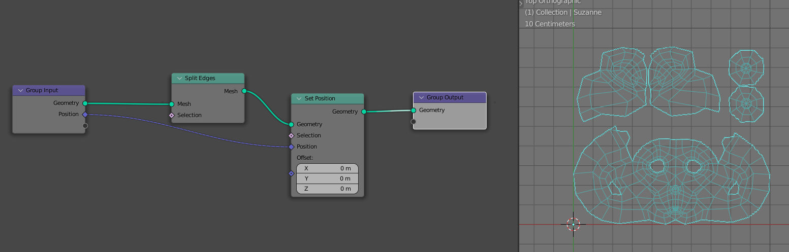
Now we can see that full mesh transformation to its UV map.
To make a transformation way visible, we can mix the coordinates of the mesh and the coordinates of its UV through the “MixRGB” node. We can use its color inputs for mixing vectors because mathematically there is no difference between three values for vertex position and three values for color.
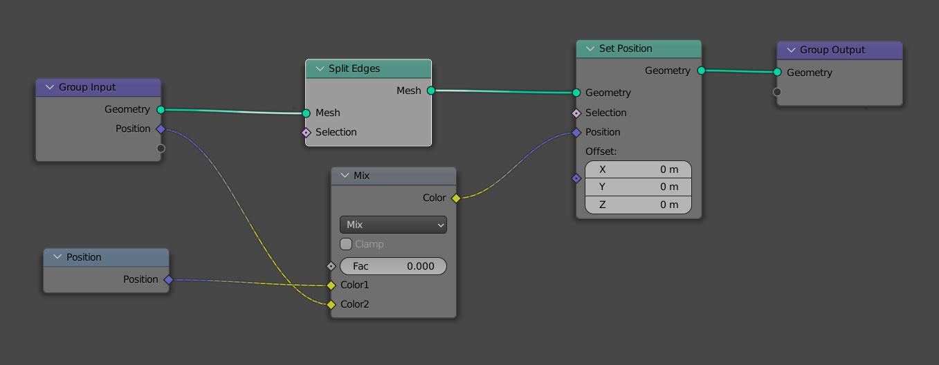
Now moving the “Factor” slider on the “MixRGB” node, we get a smooth transformation for the mesh points from one coordinate to another.
Dude,This save my ass.thx
Hi. I am trying to edit high res meshes with mathematical equations in Geometry Nodes. This means that I need to select a part, apply and tweak the equation then adjust the selection and tweak again. I have a method for selection that is fine IF the Index are in accordance with the UVs. On a real model this is never the case. UVs may be fine but Index are a mess because of the later added cuts Contact me back for more because really this “I am not a robot” thing is an inconvenience.
HI!
You can try to ask your questions in Discord. See the link in the right sidebar.
Click on the buses and then click on the planes and then …
Come on… Never mind, I have a Facebook, a web site, an email, I am on Flickr. If that’s not enough then nothing will Great tutos but I don’t think you have an answer for me.
My question was:
“How do I manage to automatically have the Index in accordance with the UVs on a model where they are not?”
As I understand it, it means how to select one UV after another automatically and give the selected vertices a rank/ID.
The only way I see how to do this is to have an animated UV map/mask that will sweep through the rectangle.
Your stunning control of the vertices in the tutorial made me think you could have some other suggestions.
If you need a number of uv-s in the geometry node tree, you can make a number of input fields and set an each uv to different inputs and next, switch or animate them inside the node tree.
Thanks, I will try.