With Blender Geometry Nodes we can easily and quickly create a fully procedural golf ball.

 .blend file on Patreon
Open the default scene. Add a plane (shift + a – Mesh – Plane). Add the Geometry Nodes modifier to it and create the initial node tree.
![]()
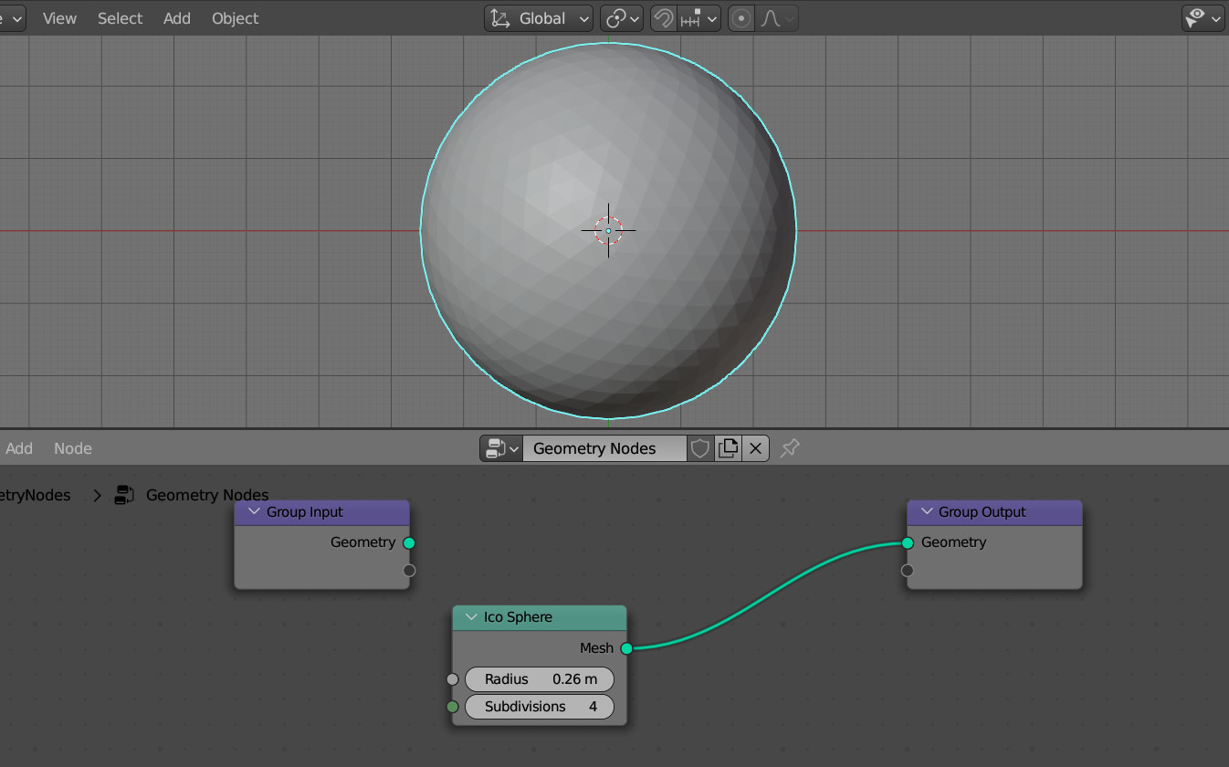
Let’s add an ICO Sphere node to the node tree (shift + a – Mesh Primitives – ICO Sphere) to create a base mesh geometry. Set the Radius parameter to 0.26 and the number of subdivisions to 4.
Disconnect the Group Input node since we don’t need the original plane geometry, and connect the ICO Sphere node with the Group Output node to work with the created sphere geometry.
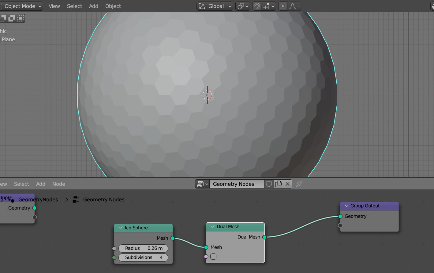
The ICO Sphere consists of triangles, which we can easily convert to hexagons using the Dual Mesh node.
Dual Mesh transforms each polygon of the mesh geometry by building new edges from the center of the polygon to the centers of its edges.
Add a Dual Mesh node (Shift + a – Mesh – Dual Mesh) to convert all ICO Sphere triangles into hexagons.
Let’s add a bit of volume to hexagon cells.
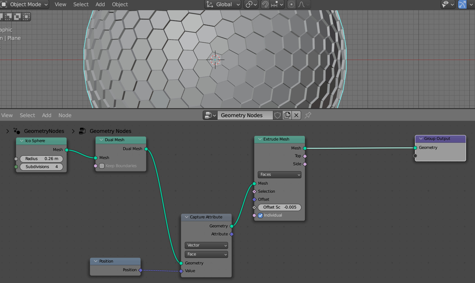
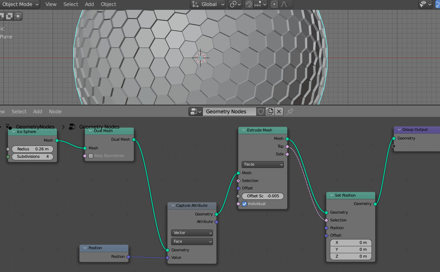
Add the Extrude Mesh node (shift + a – Mesh – Extrude Mesh) with the default “for polygons” mode – “Faces”, and set the extrusion “Offset” value to -0.005. Negative – to extrude inside the mesh.

As we can see, the cell borders are very sharp. And if we zoom in, we will see the intersections between the extruded polygons.
To add smoothness and eliminate self-intersections, let’s scale each extruded polygon towards its center.
First, we need to save the center of each polygon into the attribute.
Add a Capture Attribute node (shift + a – Attribute – Capture Attribute). Switch it to the “Vector” – “Faces” mode to work with polygons. Add a Position node (shift + a – Input – Position) and link its “Position” output with the “Vector” input of the Capture Attribute node. Thus, from the output of “Attribute” we will get the saved coordinates of the center of each polygon.
Insert the Capture Attribute node before the Extrude Mesh node to save the polygon coordinates before extruding.
To scale the polygons after extrusion, add a Set Position node (shift + a- Geometry – Set Position) to the tree. Place it after the Extrude Mesh node.
Link the “Top” output of the Extrude Mesh node with the “Selection” input of the Set Position node to resize only the extruded polygons without affecting the “walls” of the extrusion.
Add a Mix node (shift + a – Color – Mix RGB). Link its top “Color” input with the “Attribute” output of the Capture Attribute node. Link the bottom “Color” input with the “Position” output of the “Position” node.
This way, we get a transient value for each polygon’s point’s position from its current location to the previously saved polygon center. The offset from one value to another is controlled by the “Factor” parameter of the Mix RGB node.
Let’s set Factor = 0.8.
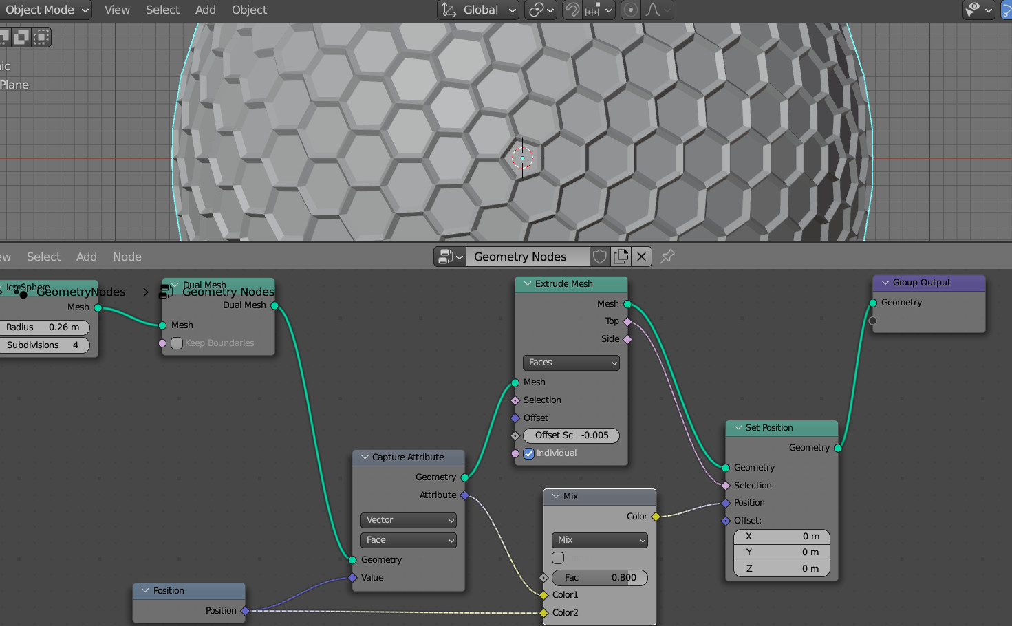
Link the “Color” output of the Mix RGB node with the “Position” input of the Set Position node.
In this way, we got beauty cells without intersections.
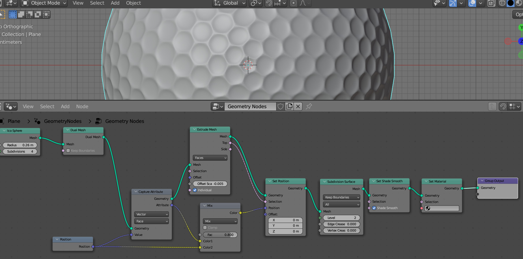
To finalize the mesh, add Subdivision Surface nodes (shift + a – Mesh – Subdivision Surface) with Level = 2 to smooth the mesh, Set Shade Smooth (shift + a – Geometry – Set Shade Smooth) to enable smooth shading and Set Material (shift + a – Material – Set Material) to assign a material.
Switch to the “Shader Editor” area and create a new material.
Let’s set up a simple material for our golf ball by changing the values in the default Principled BSDF node: Specular = 0.6 and Roughness = 0.3.
Let’s return to the Geometry Nodes area and set the created material in the Set Material node.
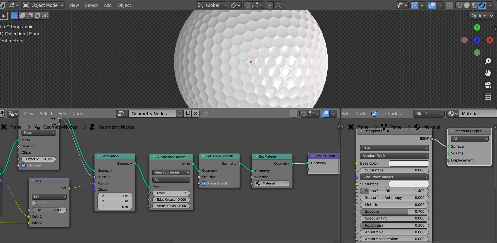
Our golf ball is ready.