When fine-tuning the finished render in “Compositing”, sometimes it is necessary to refer to the pixels coordinates of the processed image, for example, to apply effects distributed over the entire width or height of the image.
We can get the distribution factor of coordinates along with the height or width of the rendered image using texture nodes.
After rendering, switch to the “Compositing” preset, open a new window and switch it to the “Texture Node Editor” mode.
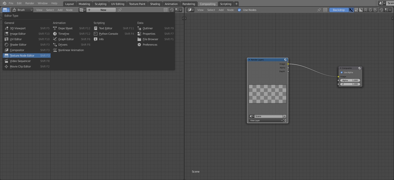
Switch to Brush texture type.
Press the “New” button to create a new texture and check the “Use Nodes” checkbox.

Delete the “Checker” node.
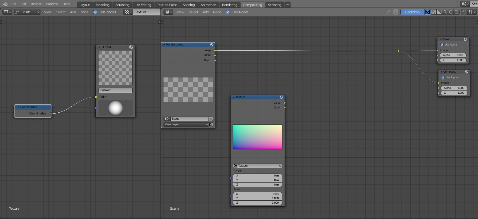
Add the Coordinates node
shift+a – Input – Coordinates
and connect its “Coordinates” output to the “Color” input of the “Output” node.

In the Compositing window, add a Texture node
shift+a – Input – Texture
and specify the texture created in the “Texture Node Editor”.
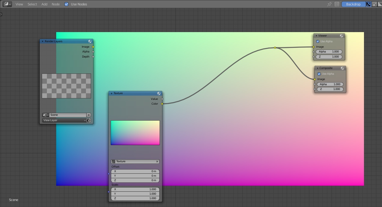
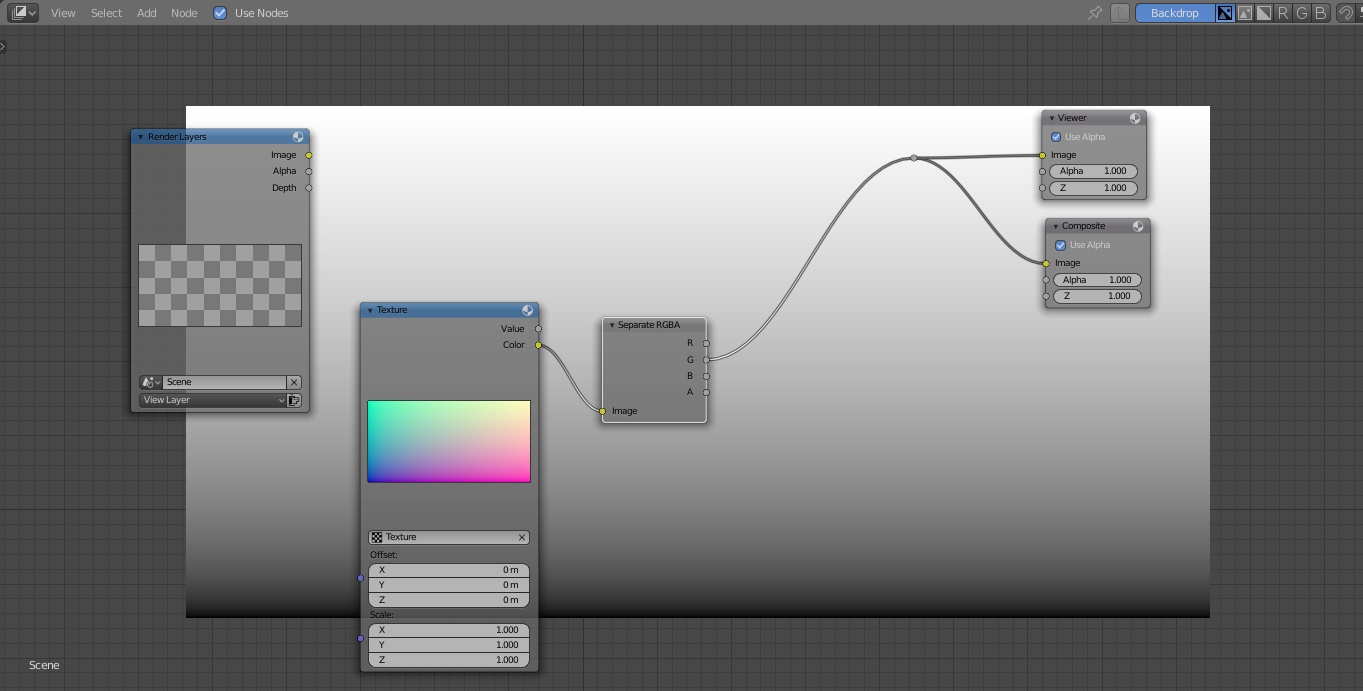
By connecting the “Color” output of the “Texture” node to the “Viewer”, we will see the distribution of coordinates along all the axes.
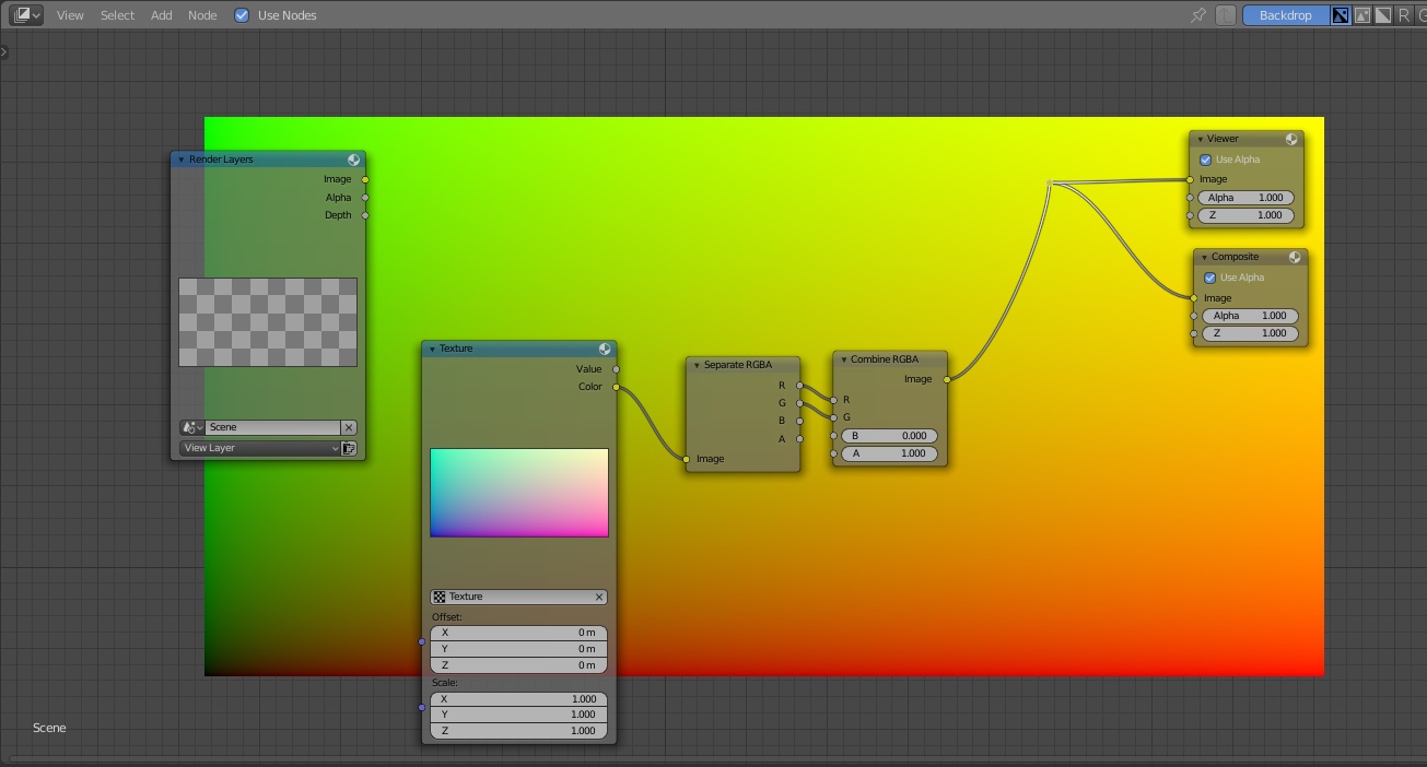
To use only the X-axis (distribution by width) or Y-axis (distribution by height), add the “Separate RGBA” node
shift+a – Convertor – Separate RGBA
and connect the “Color” output of the “Texture” node to the “Image” input of the “Separate RGBA” node.
From the “R” outputs we will get the coordinates distribution along the X-axis (image width) from 0 to 1.
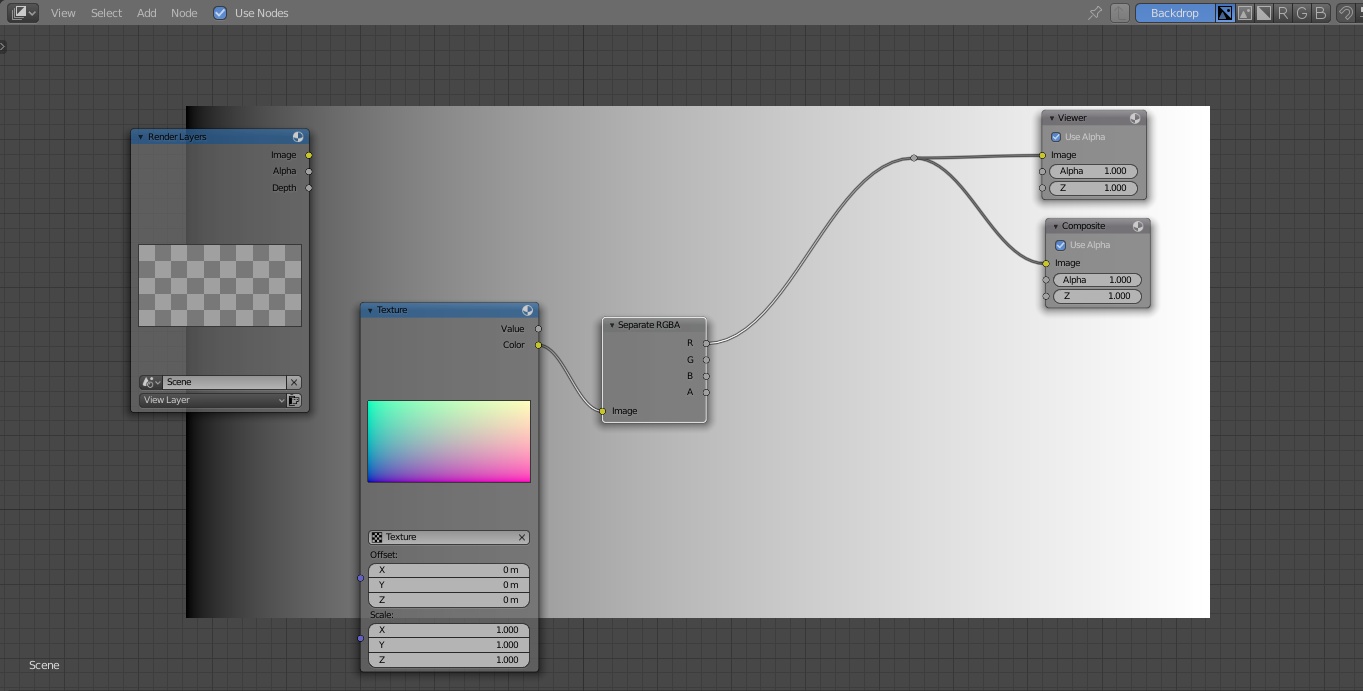
From the “G” output – the coordinates distribution along the Y-axis (height) from 0 to 1.
If we need to get the total distribution of coordinates on both axes, we can add a “Combine RGBA” node
shift+a – Convertor – Combine RGBA
and connect the corresponding “R” and “G” inputs and outputs.
Another way to get the coordinates distribution along the “X” and “Y” axes can also be obtained by creating two separate gradient textures in the “Texture Node Editor” window.
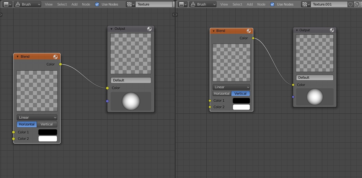
To make this, instead of the “Coordinates” node, add the “Blend” node
shift+a – Texture – Blend
Create one more texture by pressing the “New Texture” button, just like before – check the “Use Nodes” checkbox, remove the “Checker” node, and add the “Blend” node. But for this node, specify the “Vertical” distribution model.
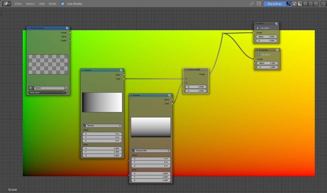
In the “Compositing” window, add another “Texture” node and specify the second texture (with the vertical distribution) in it.
Now each of these nodes gives a coordinates distribution vertically and horizontally, respectively.
If we connect the “Color” outputs of both “Texture” nodes with the “R” and “G” inputs of the “Combine RGBA” node, we will get the total coordinates distribution, as in a first way.
Hey, thanks for that.
I used that technique in my temporal denoising node group.
Specifically I had to compare the motion vector for one frame (e.g. forward vector) against the corresponding vector in the adjacent frame (e.g. reverse vector in the next frame).
I found that the Displace node could only work with pixel coordinates related to the current frame. So I worked around this by using your technique to get the pixel coordinates, and then translate/displace using the Map UV node.
https://youtu.be/jyGQIKOPwGA