By Pavel_Blend
What is this article about?
In this article, I will talk about the fluid simulator in Blender 2.80. This simulator was first added to the blender at the end of 2005, in version 2.40. Since then, it has not changed significantly (the changes were mainly in the beginning, after the introduction of the blender). The simulator code was written by a third-party developer Nils Thuerey. He wrote a fluid simulation library and named it El’Beem. The engine is voxel-based on the method of lattice Boltzmann equations. It is best suited for creating water, but it has the ability to create viscous liquids (honey, chocolate …) that are not very well implemented. Soon, a new Mantaflow simulator will be introduced into the blender (by the way, Nils Thuerey is taking part in its development).
Introduction
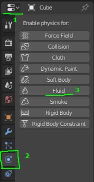
The simulator is voxel, which means that you need a domain to create fluid. A domain is a region of 3D-space, which is a parallelepiped (or cube) that is filled with voxels. Voxels are three-dimensional pixels, similar to small cubes, are the minimum unit in the simulation. To add a domain, you need to create a cube (it makes no sense to create other objects, since when creating a domain, only the dimensions of the object are taken into account). Next, go to the Properties window Physics tab and click on the Fluid button.
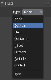
A Fluid tab appears below that stores the Type parameter. By default, this parameter is set to None. This means that the object will not participate in the simulation. You need to change this setting to Domain.
That’s all, we have created a domain. But, if we run the simulation, we get the error “No fluid input objects in the scene“. No fluid will be created. Since we have not added a source of fluid. To fix this, add any object, for example, a UV sphere (you can move it and change the scale), then in the same Physics tab, again click on the Fluid button and point Type to Fluid. Now there are two fluid objects in the scene (Domain and Fluid). Next, you can run the simulation. This is done by clicking the Bake button on the domain object (Fluid tab, Bake sub-tab). To stop the simulation, you need to click on the cross in the status bar (on which is written the number of percent of the baked simulation) the status of the bar (bottom). If you do not click on the cross, the simulator will calculate the frames from zero to the last (the Frame End parameter in the Timeline window). As a result, the sphere will create a certain volume of liquid, which (by default) under the force of gravity will fall down to the floor (if you play the animation using the Space key) and begin to flow along the lower boundary of the domain. The fact is that liquid cannot go beyond the domain. A domain is a space enclosed by “walls” that does not release liquid beyond its boundaries. The domain object itself (by default) will turn into a liquid. And in one scene there can be several domains, but liquid can be baked only when there is only one domain in the scene (otherwise the blender will give an error “There should be only one domain object“). That is, if you need more than one domain, then they need to bake the simulation in separate scenes. And to add already baked simulations to a new scene, you can add a domain object using the File> Append operator. And then you will have several liquids in the scene.
Briefly about the fluid types
- None – an object with this type not involved in the simulation. It is like a blank for creating a certain type of liquid.
- Domain – as I said, this is a space for simulation. In this space, all the miscalculations are made. Outside the domain, nothing is calculated.
- Fluid – A mesh object that has this type of fluid emits fluid from its volume once.
- Obstacle – is an obstacle – a collision for a liquid.
- Inflow – emits liquid like a water tap. That is, unlike the Fluid type, it can emit fluid not once, but continuously, creating a fluid flow.
- Outflow – is an outflow for liquid, like a drain in the bathroom. By default, liquid that enters the volume of an object of this type will be removed.
- Particle – represents settings for particles. Although the simulator is voxel, it supports the so-called secondary particles. Such as floating particles (foam), drops/splashes/splashes/tracers (various inclusions in liquids, for example, garbage in the water, berries in jam, bubbles in honey, etc.).
- Control – is a controlling object. Allows to attract or repel liquid. Useful when creating various logos from liquid, etc.
Common parameters
All of the fluid types have parameters. But some parameters are common to various types.
And the first parameter is Volume Initialization. This parameter is for Fluid, Obstacle, Inflow, Outflow types. This parameter indicates how the volume of the object mesh will be used. Three types of volume initialization can be specified:
-
- Volume. Means that the mesh volume will be used in the simulation. And in the simulation, the object will be hollow. For example, a Fluid or Inflow object will only emit fluid from its volume. And the obstacle will also be created based on the volume of the original mesh of the object. And the mesh volume will be converted to liquid voxels (in the case of Fluid/Inflow) or obstacle voxels (in the case of Obstacle).
- Shell. Uses only the shell of the source mesh of the object. That is, if you add a Fluid sphere, then in the simulation from this sphere an empty liquid sphere will be created (that is, externally the sphere will look like a sphere, and inside it will be a void, like a balloon). The wall thickness of an empty object will be one voxel.
- Both. It uses both the volume of the original mesh of the object and is covered with a shell with a layer of one voxel.
And the next general parameter is Export Animated Mesh. If this checkbox is disabled, then only the basic transformations of the original mesh object (position/rotation/scale) will be taken into account in the simulation. Otherwise, deformations of the original mesh will be taken into account (for example, deformations using reinforcement, shape keys, various modifiers that change geometry, etc.). In general, if the positions of the vertices of the original mesh change (or new vertices are created), then this checkbox should be turned on. If the original mesh object has only object transformations, this checkbox should be turned off, the simulation will be calculated faster.
On this, the general parameters are over. Next, are the unique parameters of various types of liquids.
Domain Settings
Settings sub-tab
Here is everything related to the basic settings of the simulation.
Simulation Threads – indicates the number of CPU cores that will be used during the simulation. If set to 0, then the blender will automatically determine the number of cores and will use the maximum available cores, but sometimes instead of using 4 cores, the blender will use only 2 cores. Therefore, it is advisable to manually specify this parameter if you do not want to wait longer than a miscalculation, or vice versa if you do not want the system to freeze.
Final Resolution – the resolution of the final simulation, the number of voxels of the longest side of the domain (the permissions of the other sides of the domain are calculated automatically, based on the proportions of the domain).
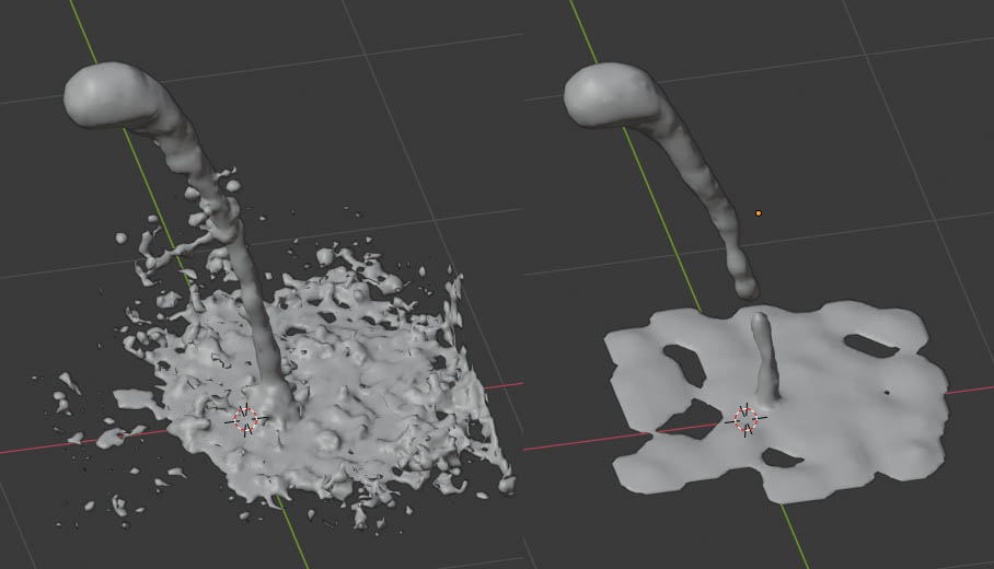
Preview – a resolution that can be used for faster playback in the 3D-view window. That is, the blender allows you to specify two permissions: Final and Preview. The first permission is the simulation permission, and the second permission is the permission for the mesh that is created for preview. The fact is that liquid voxels are converted to a mesh, and you can use the Preview parameter to specify fewer voxels to convert to a mesh. To make this easier to understand, look at the screenshot:
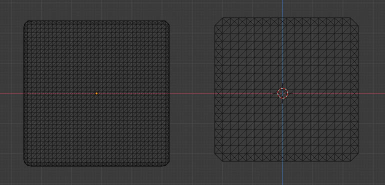
On the left in the screenshot, the mesh is generated using the Final Resolution parameter, and on the right using the Preview Resolution parameter. There are more polygons on the left, and less on the right. The same liquid voxels are converted to a mesh with different resolution variations. That is, there is one simulation of fluid voxels and two variations of the generated mesh (Final and Preview).
Render Display – indicates which fluid mesh will be displayed:
-
- Final – on the render there will be a mesh generated using the Final Resolution permission.
- Preview – on the render there will be a mesh generated using Preview permission.
- Geometry – the source domain mesh will be on the render.
Viewport – the same as the Render Display, but for a 3D-view window. That is, it indicates what will be displayed in the 3D-view window.
Time Start – the initial time of the simulation. If more than zero is set, the blender will calculate the first simulation frames in memory and will not save them to the hard drive. And as soon as the simulation time is longer than the Time Start, the blender will start writing the simulation frames to the cache. And in the status bar, the simulation progress can show 0% for a long time (until it starts writing to the cache). And it is worth noting that the simulation always starts with a zero frame.
End – the end time of the simulation. If the scene is set to FPS 30 frames per second and the final frame is 120, then for simulation in real-time, this parameter must be set to 4.0 seconds. Otherwise, the simulation will either be slowed down or accelerated. That is, this parameter indicates what time will be in the last frame. If Time Start is equal to 0.0, End is equal to 10.0, FPS is equal to 30, and the last frame of the animation (scene setup, located in the Timeline window) will be equal to 600, then the simulation in slow motion will be twice as slow (the simulation will stretch for all 600 frames).
Speed – the parameter that indicates the speed of the simulation. It is multiplied by the speed, which is calculated based on the Time Start and End parameters. And this parameter can be animated. For example, to speed up the simulation first, and then slow it down.
Generate Speed Vecotrs – this parameter tells Blender to generate speed vectors for the fluid mesh or not. That is, if the parameter is enabled, then the vectors will be generated. And these speed vectors can be used in post-processing or in Cycles Render without post-processing to add motion blur. Useful for fast-moving streams to simulate the effects of a real camera on a render (in real cameras fast-moving fluid flows look blurry).
Reverse Frames – if this option is enabled, the simulation frames will be played back. For example, if frames from 0 to 3 are baked, then if the option is disabled when playing the animation, the frames will be played in turn like this: 0, 1, 2, 3. And if you enable this option, the frames will be played like this: 3, 2, 1, 0.
Offset – Offset simulation frames. All simulation frames (fluid cache) are stored on the hard disk as *.gz files. Some frames of the scene correspond to some files from the cache. For example, frame 0 corresponds to a file from the cache under the name fluidsurface_final_0000.bobj.gz, and frame 257 corresponds to a file from the cache under the name fluidsurface_final_0257.bobj.gz. But with this parameter, you can specify other cache files to frames. Add offset to the cache. You can make sure that the first frame of the cache starts not from the zero frame, but from the tenth. To do this, set the Offset parameter to -10. Or if you want the simulation in frame zero to be 2 seconds at 30 FPS, then Offset must be set to 60.
Bake sub-tab
Everything related to the cache is located here. There are one parameter and one operator (button) in this tab:
Cache Path – the directory where the cache (baked simulation) will be stored.
Bake – button to start the simulation. When the simulation is already running, it can be interrupted in the status bar by clicking on the cross in the progress bar, or you can press the Esc key. Keep this in mind when playing already baked frames (the blender interface does not freeze during baking). It is possible to accidentally cancel the process of baking liquid and it will be impossible to resume it.
Boundary sub-tab
Here are the domain border settings and mesh generation settings. This tab stores the following parameters:
Slip Type – indicates what friction/slip the fluid will have on the domain boundary:
-
- No Slip – no slip. The fluid adheres to the boundaries of the domain.
- Free Slip – no friction. The liquid glides along the boundaries of the domain, as on ice (but without friction). If the liquid enters the domain boundary, then it will not be able to bounce off of it, since the domain boundary resets the velocity along the normal vector.
- Partial Slip – Partial Slip. When this type of slip is turned on, the parameter is added: Amount – slip amount. If 0.0, then there is no slip (the border is sticky), if 1.0, then there is no friction (100% slip). 0.5 – 50% slip and 50% friction.
Surface Smoothing – smoothing the surface of the fluid mesh (the effect is similar to the work of the Smooth modifier). The higher the value, the smoother the surface of the fluid mesh. 0.0 – no smoothing. The maximum allowed value is 5.0.
Subdivisions – with this parameter you can subdivide the grid to generate a mesh. If the parameter is less than 2, then there will be no subdivision; if it is equal to 2, then one cell of the grid to generate the mesh will be divided into 8 cells (2 vertically, two horizontally and two in depth, from one cube you get 8 cubes 2x2x2). If this parameter is set to 3, then one cell will be divided into 27 cells (3x3x3), with 4 by 64 (4x4x4), etc. For example, if the resolution of the simulation is 100x50x25, and the Subdivisions is 2, then the resolution of the grid for generating the fluid mesh will be 200x100x50, respectively. In general, this option allows you to create a higher poly fluid mesh.
Remove Air Bubbles – if this option is enabled, air gaps are removed between obstacles and the surface of the liquid by adding additional voxels to generate the mesh. To better understand this parameter, see the following image:

The option is enabled on the left and disabled on the right. As you can see, when the option is enabled, the fluid mesh penetrates the obstacles so that there are no air gaps.
Particles sub-tab
This tab with particle settings.
Tracer – the number of particles of tracers. It can be bubbles in honey, pieces of berries in jam, various kinds of inclusions in liquids that float in it. I will tell you about tracers below.
Generate – This parameter is ambiguous. Firstly, it affects the number of generated floating particles (foam) and the number of bursts (Drops). But the second value of this parameter takes effect when the Subdivisions value (Boundary sub-tab) is higher than 1. If the Generate parameter is greater than zero and the Subdivisions parameter is greater than or equal to 2, then sprays are generated that are implemented as geometry (in the form of polygons). The figure below shows an example with and without geometric particles:
In the picture, two simulations have the same parameters, except for the Generate parameter. On the left, this parameter is set to 10.0, and on the right, 0.0.
World sub-tab
The parameters of the simulation space are stored here. By default, two parameters are not active. These parameters are Gravity and World Size Meters.
Gravity – gravity in a fluid simulation. By default, scene gravity is used. If gravity is disabled in the Scene tab of the Properties window, then the gravity value can be specified in this parameter.
World Size Meters – the real domain size in meters. By default, the size of the source domain object is used. If you set the units to None in the Scene tab of the Properties window, you can specify the domain size value in this parameter.
Viscosity sub-tab
Stores viscosity settings. In the header of the Viscosity panel, you can select presets: Water, Oil, Honey.
Base – base value of viscosity. The higher this value, the more viscous the liquid.
Exponent – the negative exponent of the viscosity value. That is, the Base value is multiplied by 10 to the power minus the Exponent. For example, if Base is 4 and Exponent is 3, then the viscosity will be 4 * 10 ^ (-3). The exponent is needed to make it easier to indicate too low or too high viscosity values. The higher this parameter, the lower the viscosity (i.e. there is an inverse relationship).
Fluid Options
Volume Initialization – a general parameter (described above).
Export Animated Mesh – is also a general parameter, which I have already described above.
Initial Velocity XYZ – a vector indicating the initial fluid velocity. If equal to (1.0, 0.0, 0.0), then the initial fluid velocity will be one unit (meter/blender unit) along the X-axis.
Obstacle Options
Volume Initialization – described above.
Export Animated Mesh – described above.
Slip Type – similar to the domain parameter with the same name. But in the domain, this parameter is responsible for the friction against the walls, and in Obstacle, it is responsible for the friction on the surface of the obstacle. For Free Slip the liquid will glide over the surface of the obstacle, No Slip – will stick, Partial Slip – will be the intermediate between the absence and presence of friction (partial friction is indicated by the Amount parameter, as in the domain).
Impact Factor – this parameter indicates how the obstacle acts on the fluid. This parameter takes effect if the obstacle object is moving. If the value is 1.0, the obstacle in the usual way collides with the liquid and pushes it with a standard force. If the value is greater than 1.0, then the force that the obstacle gives to the liquid will be increased. If the value is negative, then when the obstacle is inserted into the liquid, the liquid will be removed, and when the obstacle is removed from the liquid, all the liquid that is on the surface of the obstacle will be repelled from it. Experiment with this parameter and understand what I mean. This parameter can be used to adjust the mass of the obstacle. That is, an obstacle can be made more or less massive than it actually is.
Inflow Options
Flow checkbox in the panel title – enables or disables the emission of fluid from the Inflow object. For example, you can turn off (like a water tap) a fluid source, and then turn it on again. This parameter is animated, like most parameters.
Volume Initialization – described above.
Export Animated Mesh – described above.
Local Coordinates – use the local coordinates of the source object to indicate the direction of the initial velocity of the fluid source. Otherwise (if turned off) the global coordinates of the scene will be used. For example, if the fluid source is rotating, it is advisable to enable this parameter.
Initial Velocity XYZ – the same as for the Fluid object. Indicates the initial velocity and direction of the fluid source.
Outflow Options
Flow checkbox in the panel title – enables or disables the outflow object. Similar to the same checkmark of the Inflow object. That is, the outflow can be turned off from the simulation, and then turned on again.
Volume Initialization – described above.
Export Animated Mesh – described above.
Particle Options
Settings sub-tab
Influence Size – indicates whether the secondary particles will be of different sizes. With a value of 0.0, all particles will have the same size. At 1.0 – the particle size will be different and ranges from 0.2 to 2.0. If the value is higher than 1.0, then the particle size difference will be even greater.
Influence Alpha – if this value is greater than zero, then the transparency values of the particles change depending on their size.
Drops – includes the generation of droplet particles (those particles that are located above the surface of the liquid).
Floats – includes the generation of foam particles (those particles that are on the surface of a liquid).
Tracer – includes the generation of particle tracers (those particles that are interspersed in a liquid).
You can create three Particle objects (for greater control) and activate different checkboxes for each. Or you can create one Particle object and activate all the checkboxes in it.
A fluid system is created for the Particle object (it has fewer settings than a regular particle system). It is located in the same place as ordinary particles (the Particles tab).
Cache Sub-Tab
It has only one parameter:
Path – indicates where to look for the particle cache (the particle cache is stored in the files fluidsurface_particles _ ####). Typically, this path should match the Cache Path parameter of the domain object.
Control Options
Quality – Main quality. The miscalculation is slower with higher quality.
Reverse Frames – flip the animation of the Control object back to front. For example, there are 4 frames of animation: 0, 1, 2, 3 of the Control object. If the checkbox is off, the animation will play in the same order. And if enabled, then the frames will follow in the reverse order: 3, 2, 1, 0.
Time Start – indicates the initial time of the monitoring object. For example, if you want the Control object to not immediately begin to attract liquid, but after a certain time, then increase this parameter.
Time End – the end time of the controlling object. If you want the liquid to be attracted to the last frame, set this parameter to the same value as the domain object in the Time End parameter. If you want to stop attracting fluid in the middle of the simulation, lower this parameter (so that it is below the Time End parameter of the domain object).
Attraction Strangth – gravity. Positive values attract liquid, negative values repel.
Attraction Radius – the radius of the force field on which the force of gravity acts.
Velocity Strength – this parameter is responsible for how the speed of the liquid depends on the speed of the Control object.
Velocity Radius – the radius of the force field affected by the speed of the Control object.