With Geometry Nodes in Blender, we can quickly distribute many small objects along the boundaries of a single large mesh and adjust the size of the footprint or area.

 .blend file on Patreon
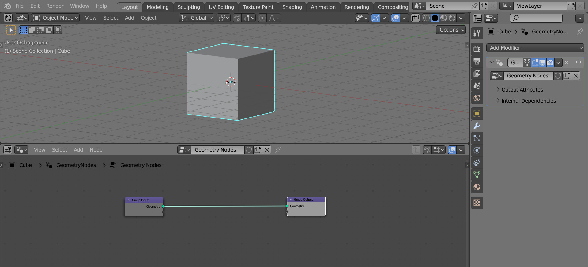
Add a cube to the scene (shift + a – Mesh – Cube), assign the Geometry Nodes modifier to it, and create the initial node tree by pressing the “New” button.
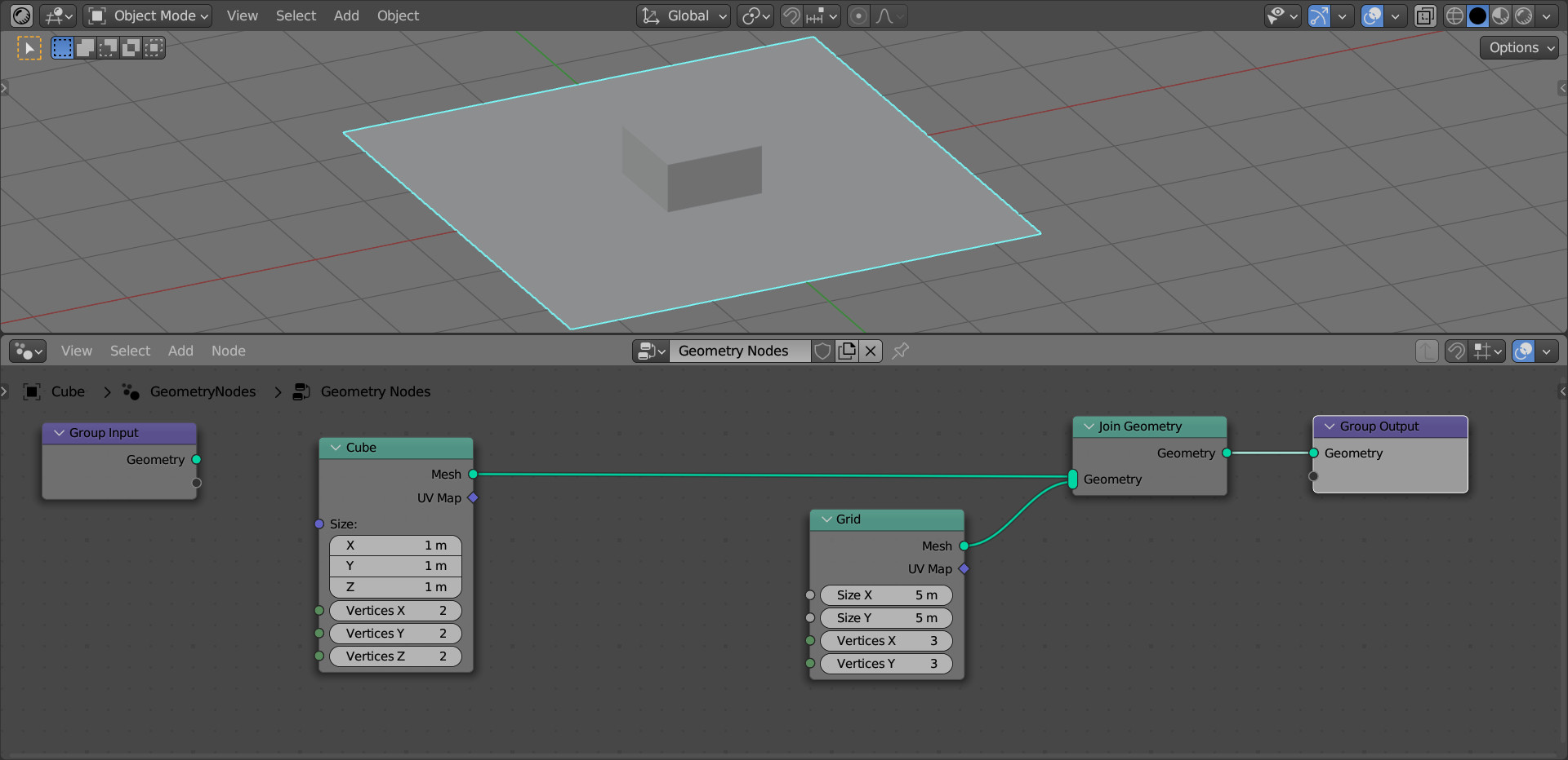
We will not use the original cube geometry, let’s replace it completely with nodes.
Add nodes with cube geometry (shift + a – Mesh – Primitives – Cube) and plane geometry (shift + a – Mesh – Primitives – Grid) to the node tree and merge them using the Join Geometry node (shift + a – Geometry – Join Geometry).
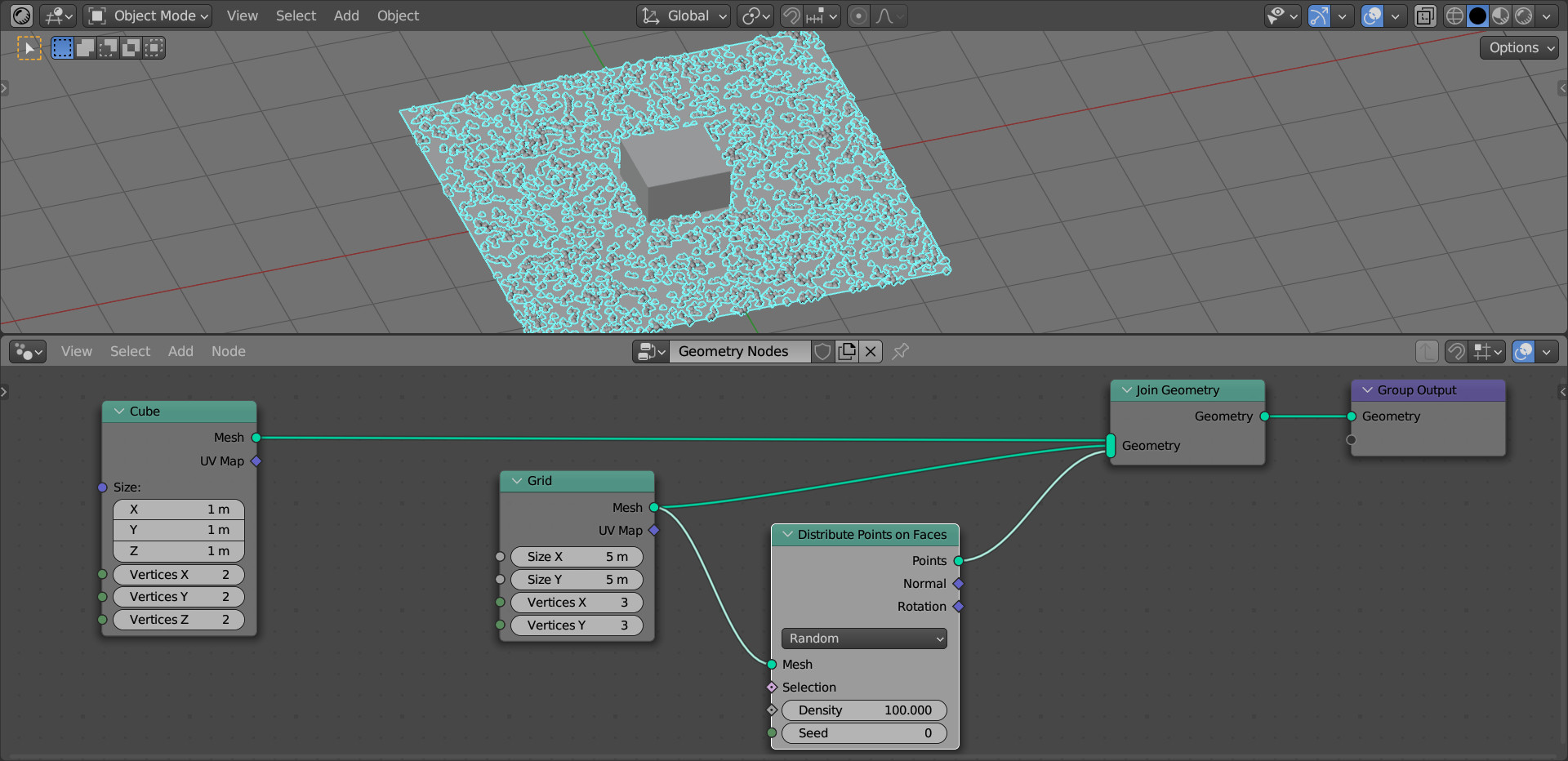
Fill the plane with points over the entire area. Add a Distribute Points on Faces node (shift + a – Point – Distribute Points on Faces), link its Mesh input with the Mesh output of the Grid node, and link the Points output with the Join Geometry node.
Increase the number of points by raising the value of the Density field to 100.
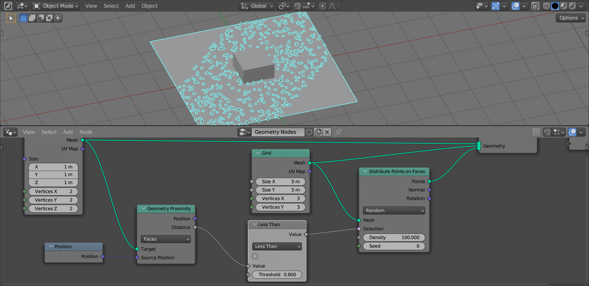
To place points only along the faces of the cube, the Geometry Proximity node will help us. It is designed to calculate the minimum distance from the mesh geometry.
Add this node (shift + a – Geometry – Sample – Geometry Proximity).
Our cube is the original geometry from which we take the distance. Link the Mesh output of the Cube node with the Target input of the Geometry Proximity node.
In the node parameters, set the “Faces” mode, so that the distance is calculated from the faces of the cube.
We can get the distance value from the geometry of the cube from the Distance output. To clip points scattered on the plane, depending on this distance, link the Distance output with the Selection input of the Distribute Points on Faces node.
Since we need to count the distance from the cube faces as a position attribute, add a Position node (shift + a – Geometry – Read – Position) and connect it to the Source Position input of the Geometry Proximity node.

So far, nothing has changed. This is because we did not set the boundary along which we will cut off extra points.
Add a Math node (shift + a – Utilities – Math) right after the Geometry Proximity node. Switch it to the “Less Than” mode and try to change the “Value” parameter.
As we can see, some of the points were cut off, but the cutoff was done very roughly. This happened because the culling by the Selection field in the Distribute Points on Faces node is performed by the polygons of the geometry on which the points are placed.
Increase the resolution of the plane (Grid) by increasing the values in the VerticesX and VerticesY fields of the Grid node.
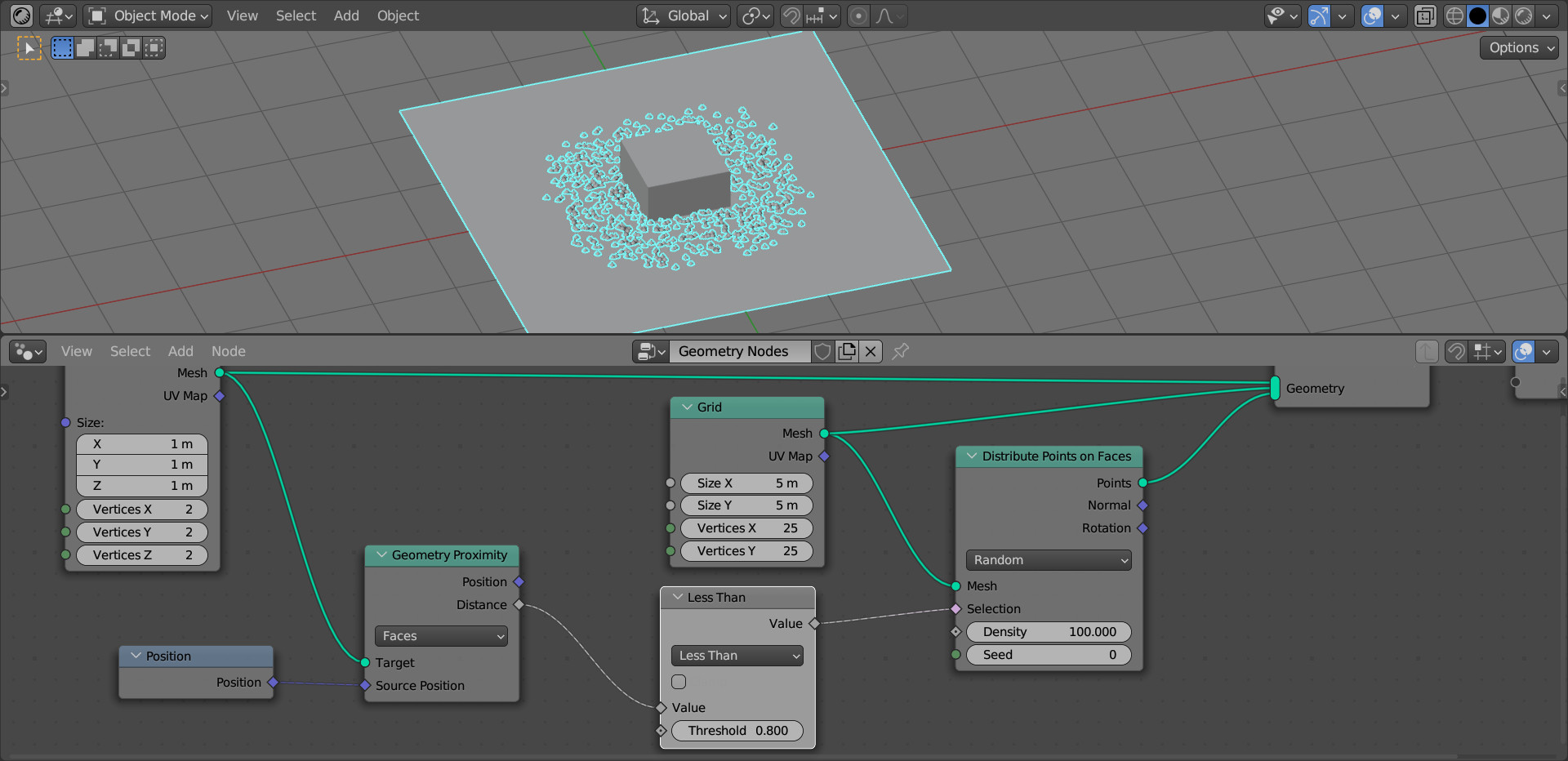
By adjusting the number of points with the “Density” parameter of the Distribute Points on Faces node and the border of their location with the “Value” parameter of the Math (Less Than) node, we can achieve the required filling quality.
Switching to the Wireframe mode, we can see that the points are cut off not only from the outside of the cube, but also from the inside.

To turn the points into real geometry, add an Instance on Points node (shift + a – Instances – Instance on Points) right after the Distribute Points on Faces node.
Link its “Instances” input with any geometry output node, for simplicity, connect this input with the “Mesh” output of the Cube node and scale down instances size by tuning the “Scale” field.
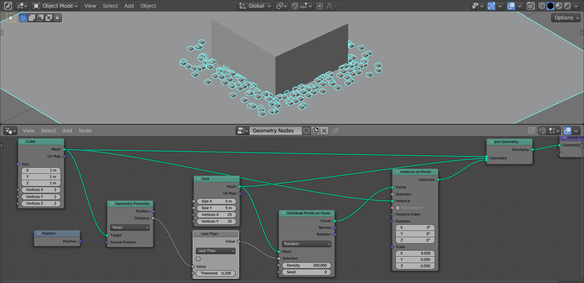
As a result, we got a cube surrounded with small cubes around the perimeter.