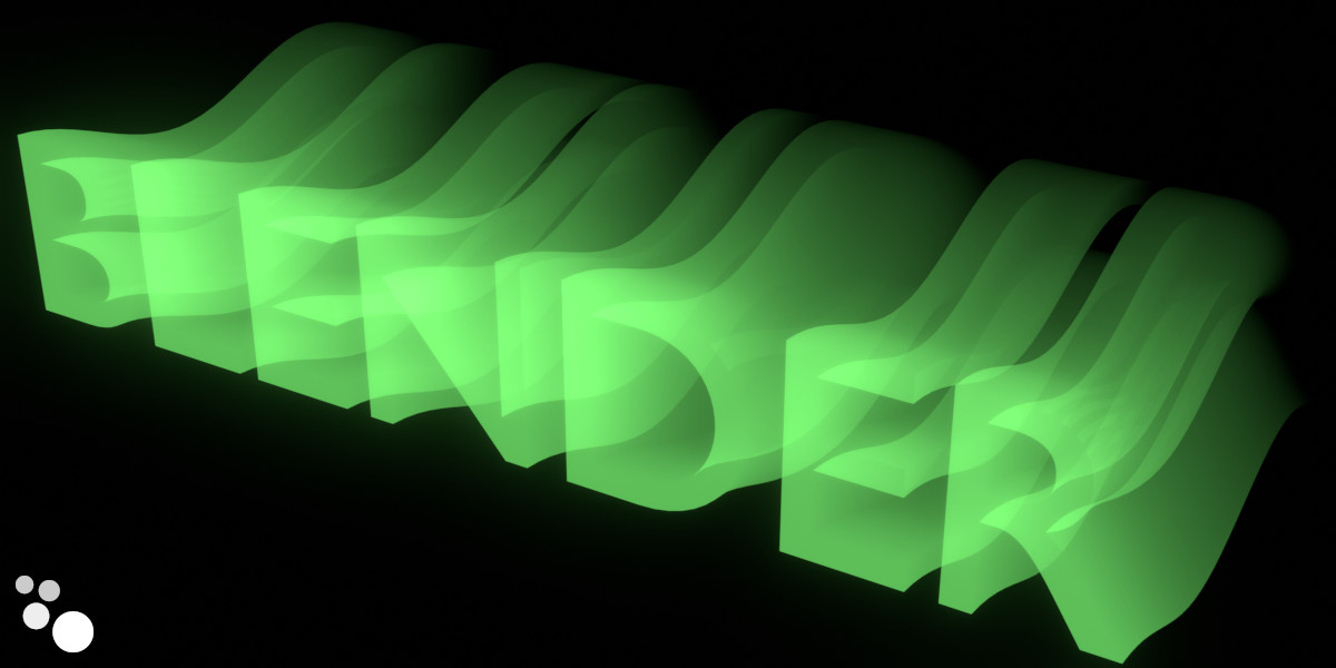
By combining text extrusion with a simple mathematical operation, we can get an interesting effect of volumetric text in waves.
 .blend file on Patreon
To start, add a cube to the scene (shift + a – Mesh – Cube), append a Geometry Nodes modifier to it and initialize the node tree by clicking on the “New” button.
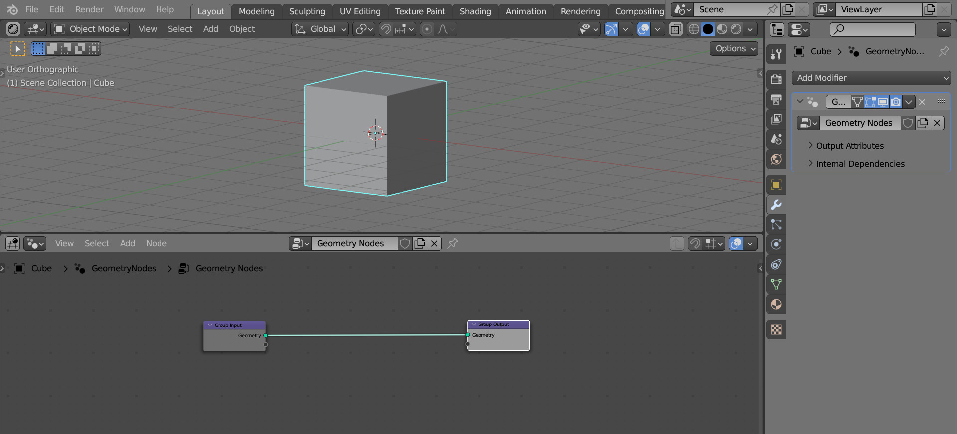
We don’t need the original cube geometry, we will use text.
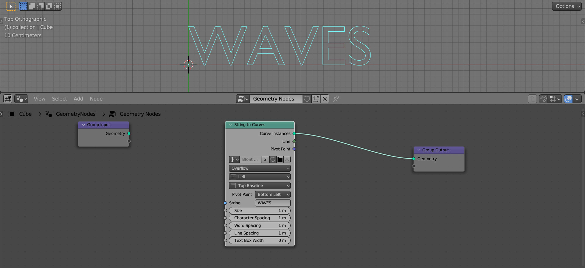
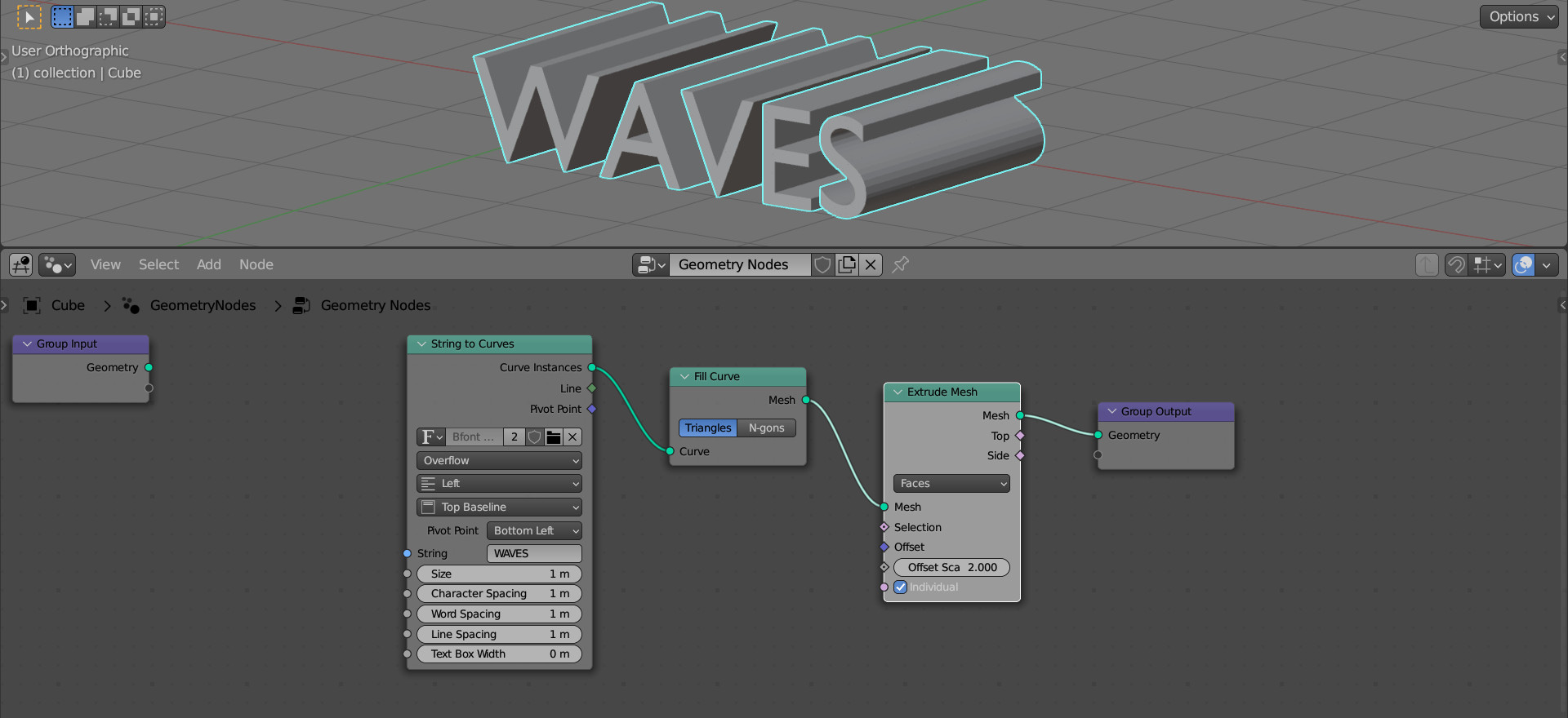
Add a String to Curves (shift + a – Text – String to Curves) node to the main branch of the node tree. Type some text to the “String” field.
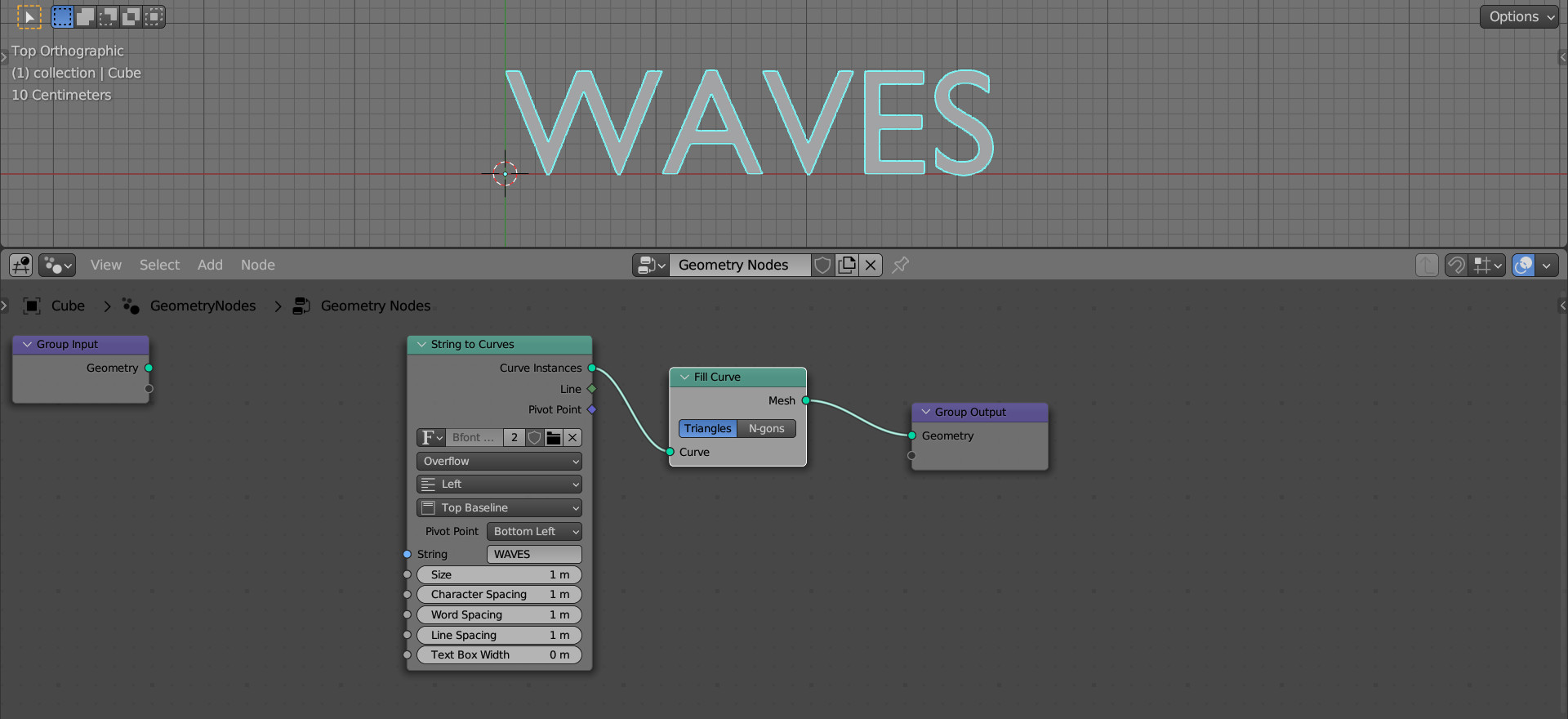
Fill the curves with the Fill Curve node (shift + a – Curve – Fill Curve) by adding it right after the String to Curves node.
To add volume to the text, we can use the Extrude Mesh node (shift + a – Mesh – Extrude Mesh). Add it after the Fill Curve node. In the “Offset Scale” field, type a value of 2.0 for a bit longer extrude.
For convenience, we can rotate the entire object with text by 90 degrees around the X-axis (r – x – 90).
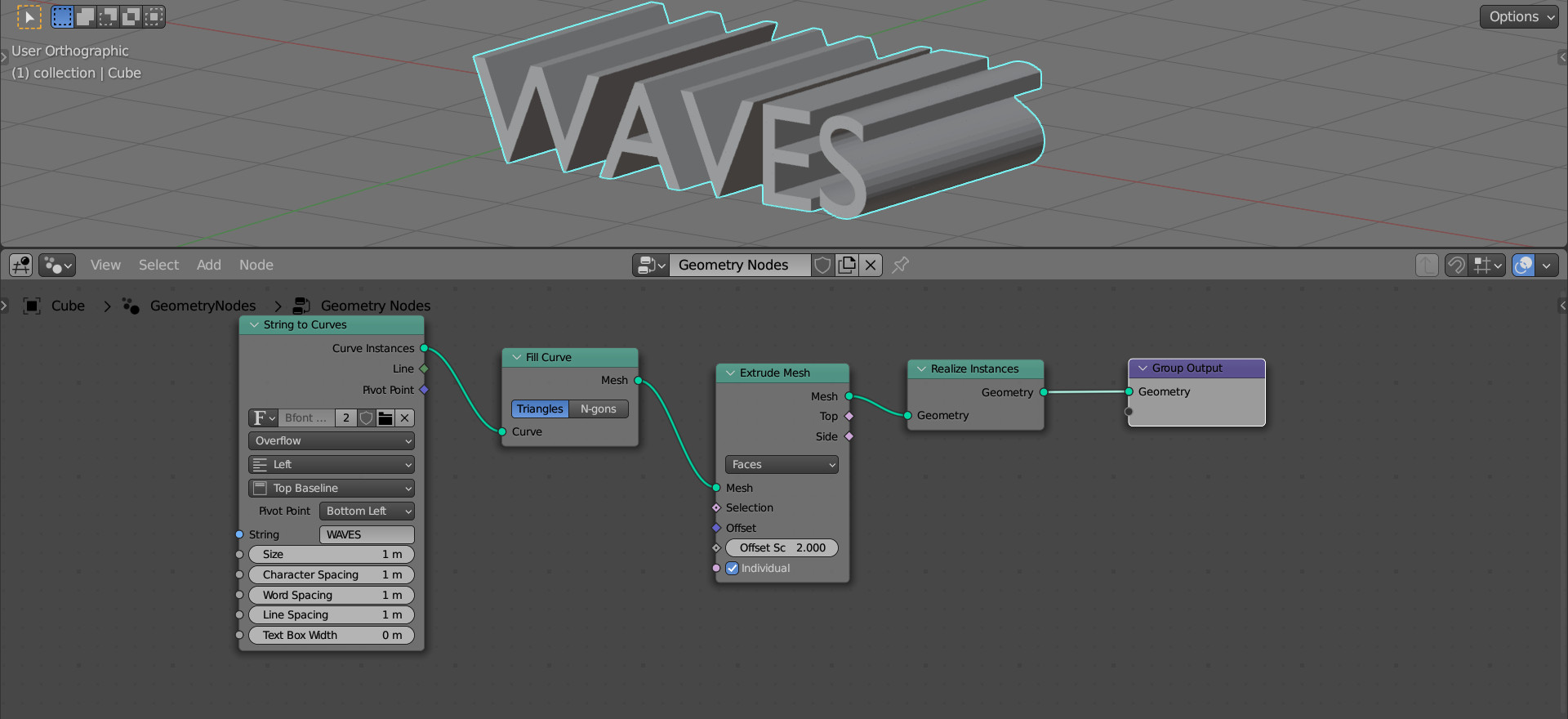
To work with the geometry of the text, add a Realize Instances node (shift + a – Instances – Realize Instances) after the Extrude Mesh node.
Now, instead of instances of letters, we have a single mesh.
At present, all the points of the mesh geometry are placed on the front and back planes of the mesh. To make waves, we need points in the middle. Let’s subdivide the mesh using the Subdivide Mesh node (shift + a – Mesh – Subdivide Mesh), adding it after the Realize Instances node.
Set the subdivision level to 5.
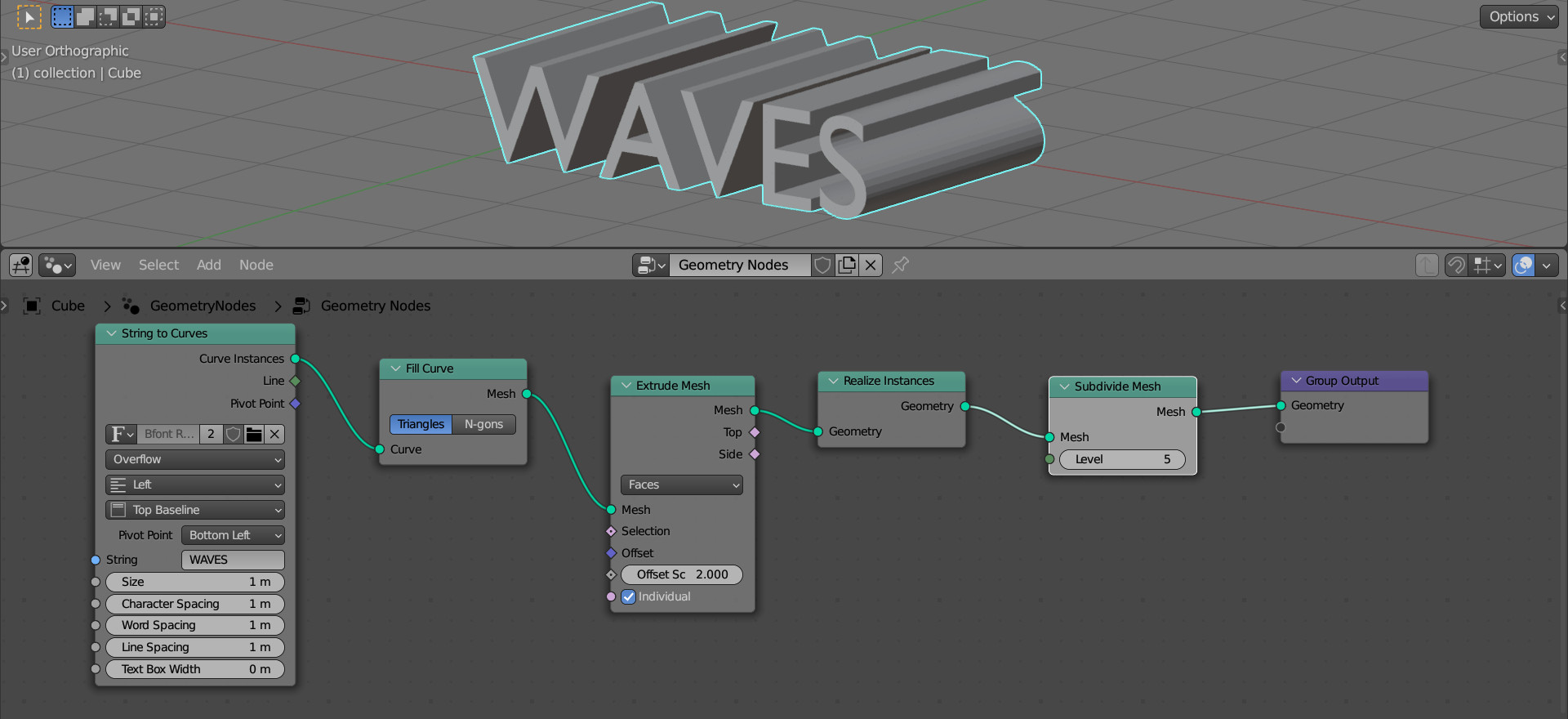
Now the mesh has enough points on the sides to manipulate them.
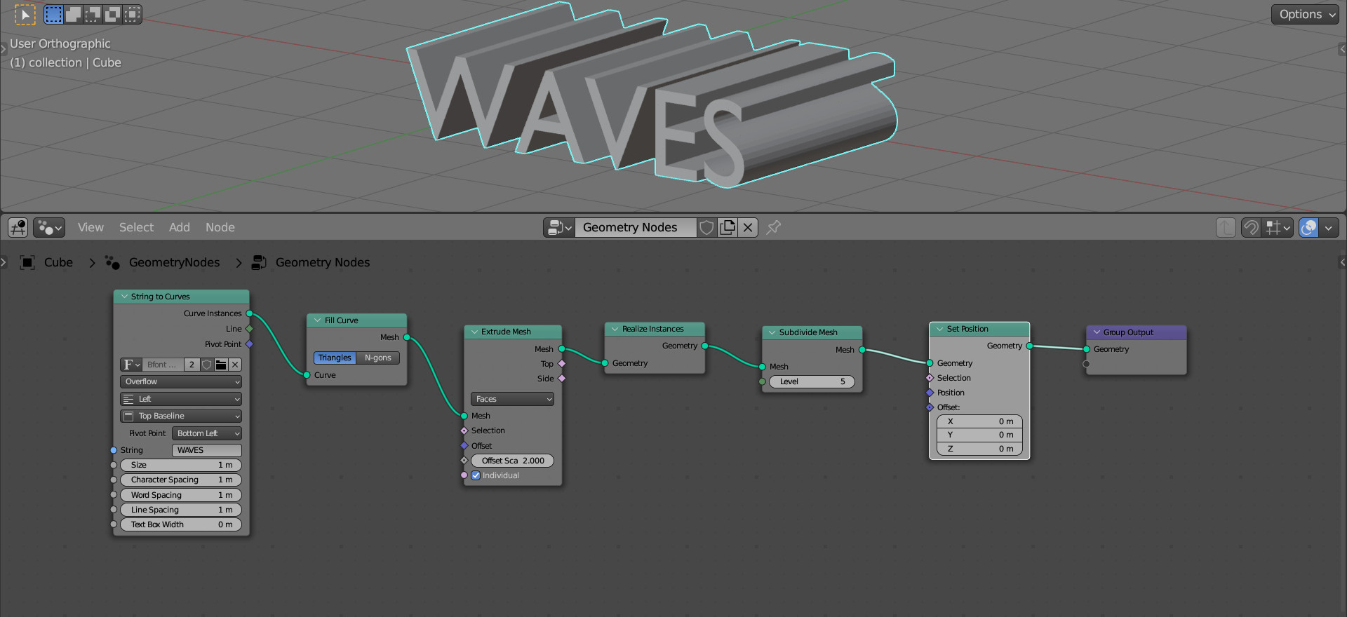
Add a Set Position (shift + a – Geometry – Set Position) node after the Subdivide Mesh node. With it, we will control the position of the points.
To make a wave, each point of the mesh must be shifted along the local Y-axis using the sine function. The argument of the sine function will be the position of the point along the extrude direction – the local Z axis.
We can get the position for each point from the Position node (shift + a – Input – Position).
To get point offsets separately along the Y and Z axes, use the Separate XYZ node (shift + a – Vector – Separate XYZ).
We can get the sine function using the Math node (shift + a – Utilities – Math) in the “Sine” mode.
And combine the offsets along the local Y and Z axes back into a single vector using the Combine XYZ node (shift + a – Vector – Combine XYZ).
Let’s add and sequentially link all these nodes. Link the result of the calculation to the “Offset” input of the Set Position node.
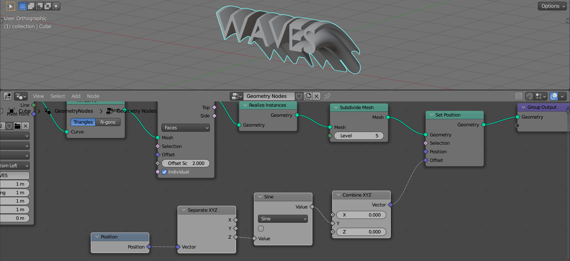
Now when we move along the local Z-axis of the mesh, (along the extrude direction), the position of each point is shifted along the local Y-axis by a sine value, making the wave we need.
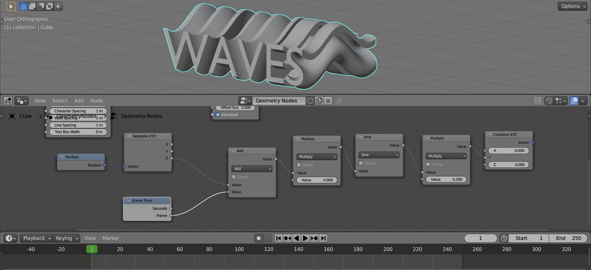
To control the amplitude and frequency of the wave, add two more Math nodes before and after the Sine node (shift + a – Utilities – Math) in the “Multiply” mode.
The left node is responsible for the frequency of the waves, put the value 4.0 in its free field. The right one – for the height of the wave, type the value of 0.1 in its free field.

Thus, we have obtained the required waveform.
Let’s add some dynamics – connect the position of the wave with the timeline.
To get the current animation frame from the timeline, add a Scene Time node (shift + a – Input – Scene Time).
Add another Math node (shift + a – Utilities – Math) in the “Add” mode after the Separate XYZ node. Link the “Frame” output of the Scene Time node with its free input.
Now, we add the value of the current frame to each shift of points.
We can see the movement if we start the animation now.
However, the movement is very jerky. To make it smoother, let’s reduce the added value of the frame by 10 times.
Add a Math node (shift + a – Utilities – Math) in the “Multiply” mode after the Scene Time node. In the remaining free field, type the value 0.1.
Now the animation looks much nicer.