In order to bind the “face” direction of one object to another object, Blender usually uses the Track To constraint. However, if necessary, we can make the same tracking constraint using Geometry Nodes.
 .blend file on Patreon
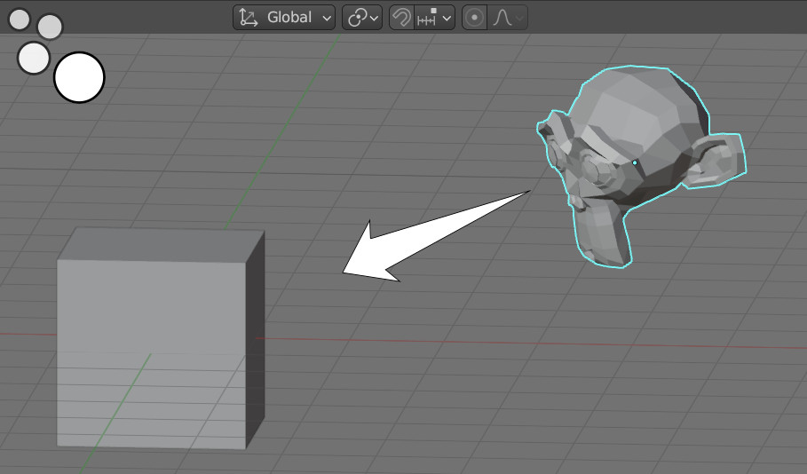
Add a cube to the scene (shift + a – Mesh – Cube). Next add Suzanne mesh to the scene (shift + a – Mesh – Monkey). Now let’s set up Suzanne with Geometry Nodes so that she always “looks” at the cube.
Add the Geometry Nodes modifier to the Suzanne mesh and create the initial tree of nodes by clicking on the New button.
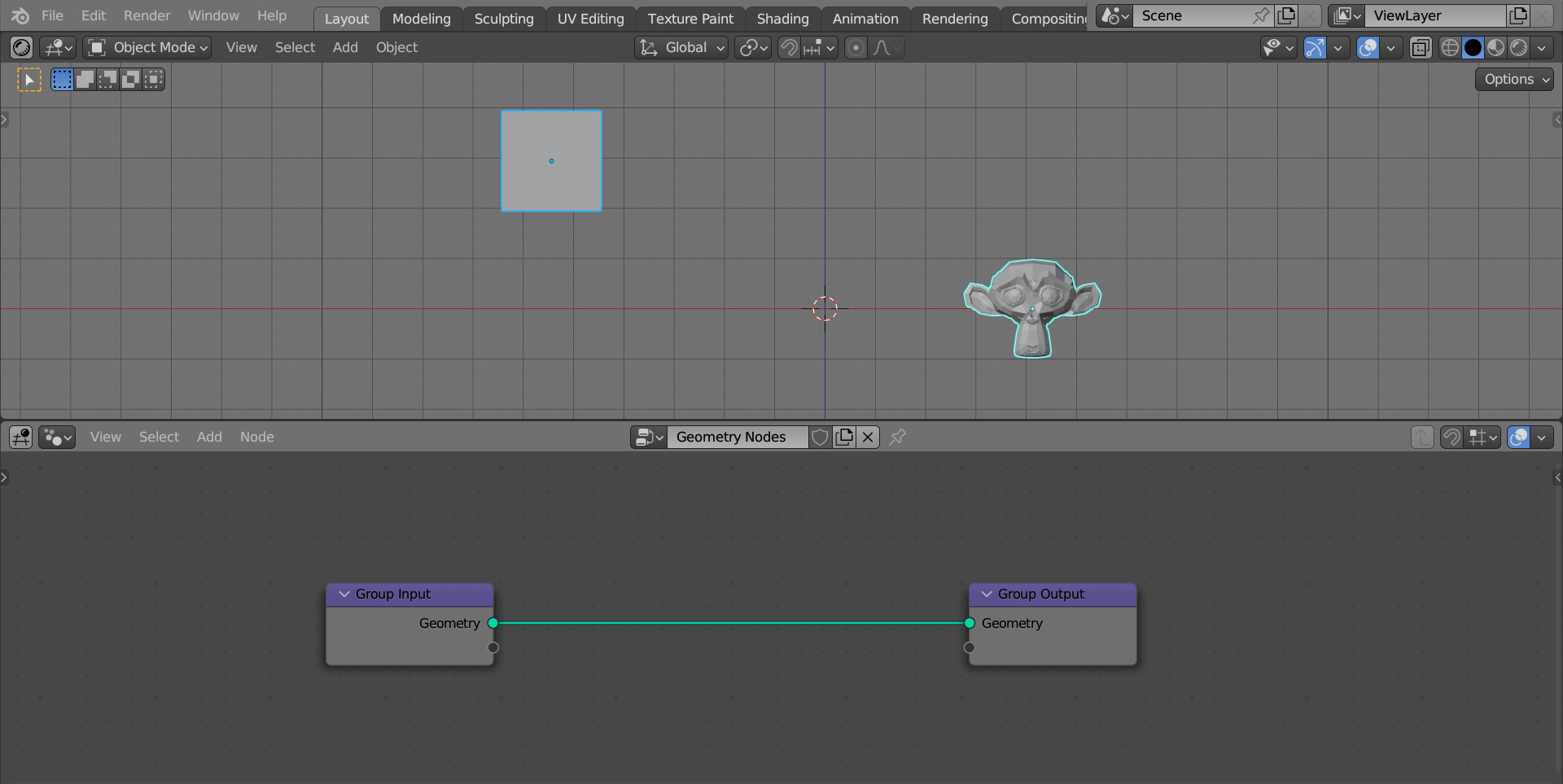
First, we need to get a vector that looks from Suzanne’s origin point to the cube’s origin point.
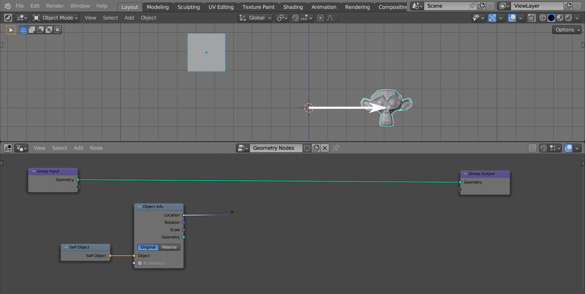
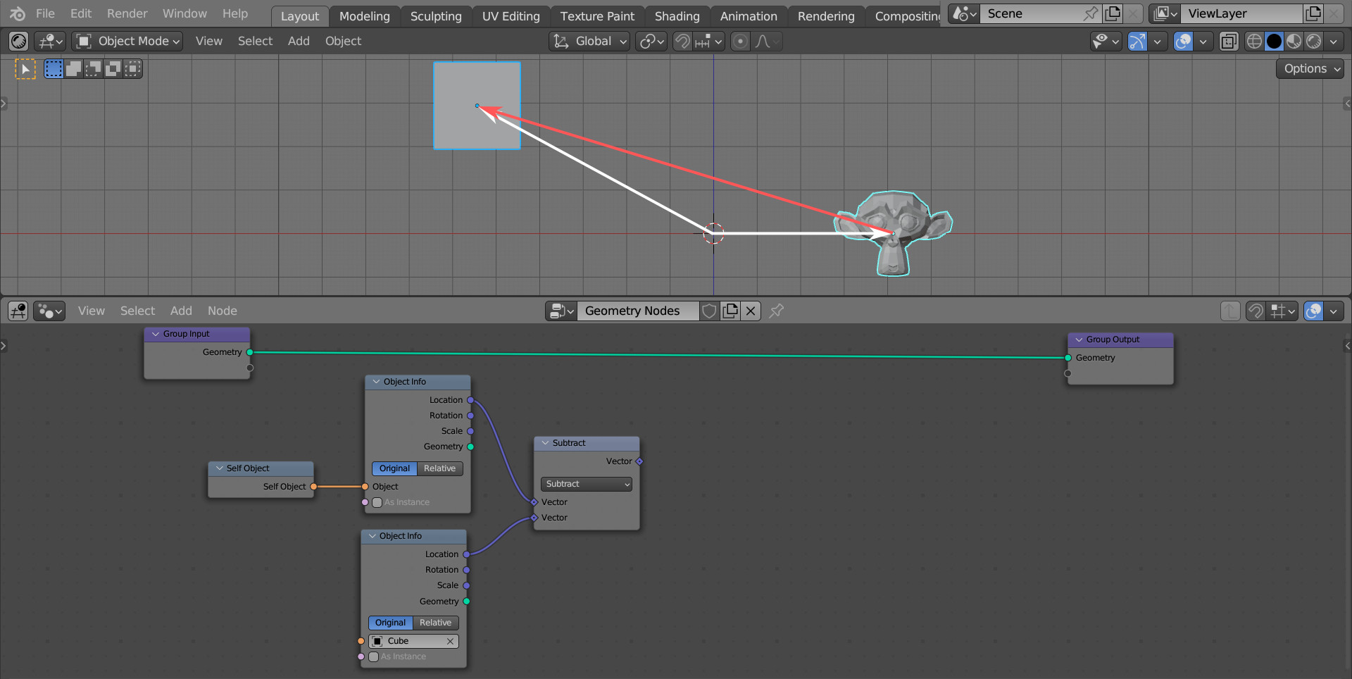
To get a vector from the center of the scene to Suzanne’s origin, add an Object Info node (shift + a – Input – Scene – Object Info).
To get data for the current object (Suzanne), add a Self Object node (shift + a – Input – Scene – Self Object) and link its “Self Object” output to the “Object” input of the Object Info node.
Now, from the “Location” output of the Object Info node, we will get a vector from the scene’s center to Suzanne’s origin.
Add another Object Info node (shift + a – Input – Scene – Object Info) and select the Cube object in its “Object” field. From the “Location” output of this node, we can now get a vector from the center of the scene to the origin point of the cube.
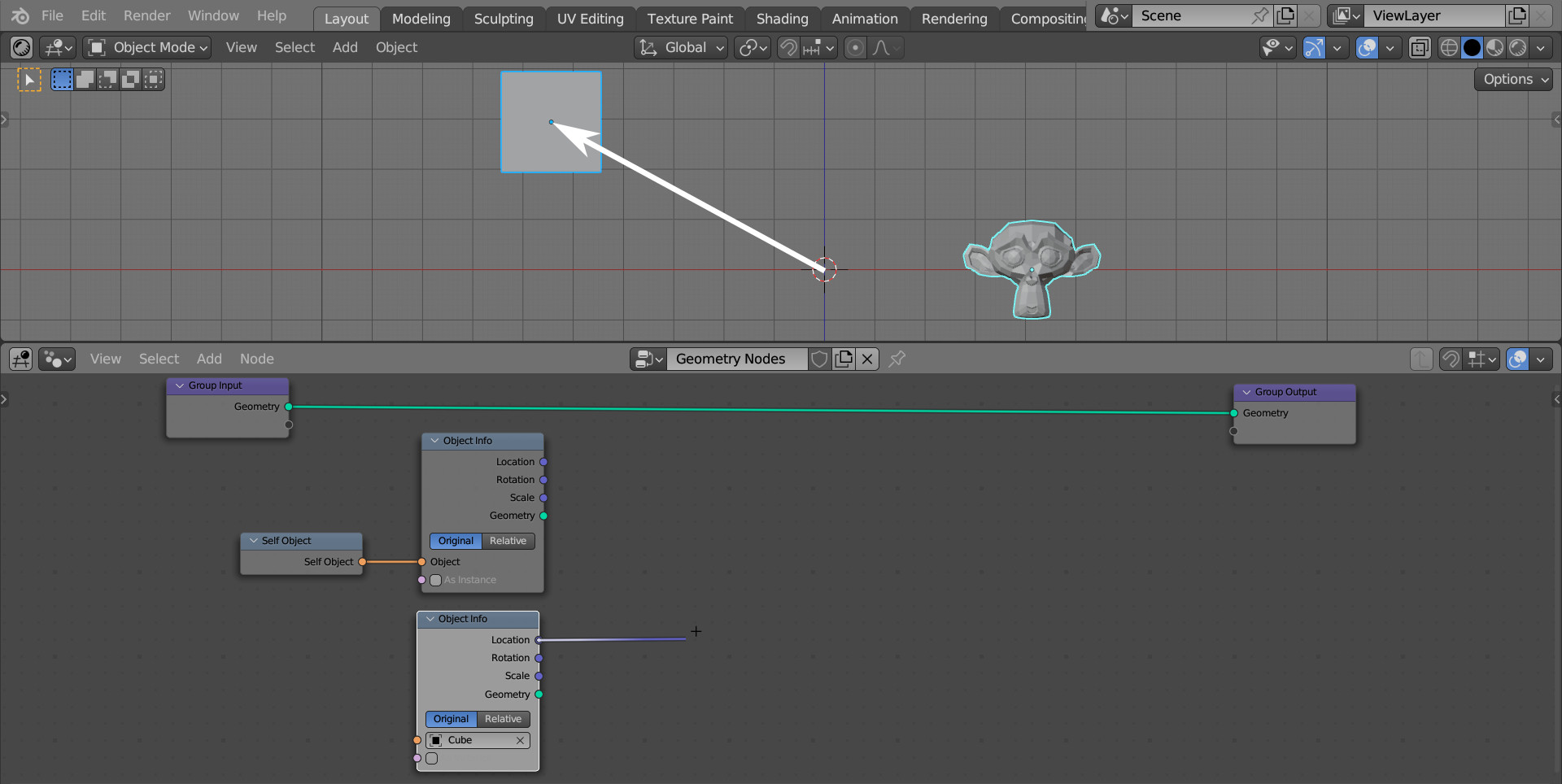
Now, if we subtract one vector from another, we will get the vector from Suzanne’s origin to the cube’s origin.
Add a Vector Math node (shift + a – Utilities – Vector – Vector Math) and switch it to the “Subtract” mode. Link the “Location” outputs of the Object Info nodes with the “Vector” inputs of the Vector Math node.
To rotate Suzanne’s direction along the resulting subtracted vector, add an Align Euler to Vector node (shift + a – Utilities – Rotation – Align Euler to Vector). Fill its “Rotation” input with the vector of Suzanne’s current rotation, which we can take from the “Rotation” output of the Object Info node (for Suzanne). The vector along which we want to rotate Suzanne link with the “Vector” input.
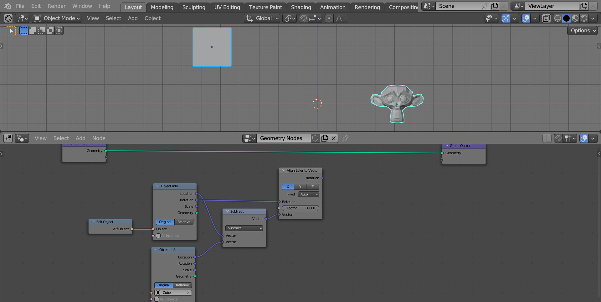
Now we have Suzanne’s rotation formula, it remains to apply it to the object itself.
Convert Susanna’s mesh into an instance to simplify the calculations. Add a Geometry to Instance node (shift + a – Geometry – Geometry to Instance) to the main branch of the node tree.
To rotate an instance, we can use the Rotate Instances node. Add it (shift + a – Instances – Rotate Instances) to the main branch of the node tree after the Geometry to Instances node.
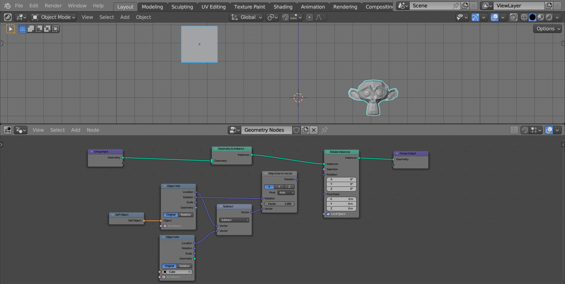
And finally, apply the calculated rotation by connecting the “Rotation” output of the Align Euler to Vector node to the “Rotation” input of the Rotate Instance node.
Since we need Suzanne to look at the cube by “face” – to have the Y-axis of the object directed at the cube, switch the axes of the Align Euler to Vector node to the “Y” mode.
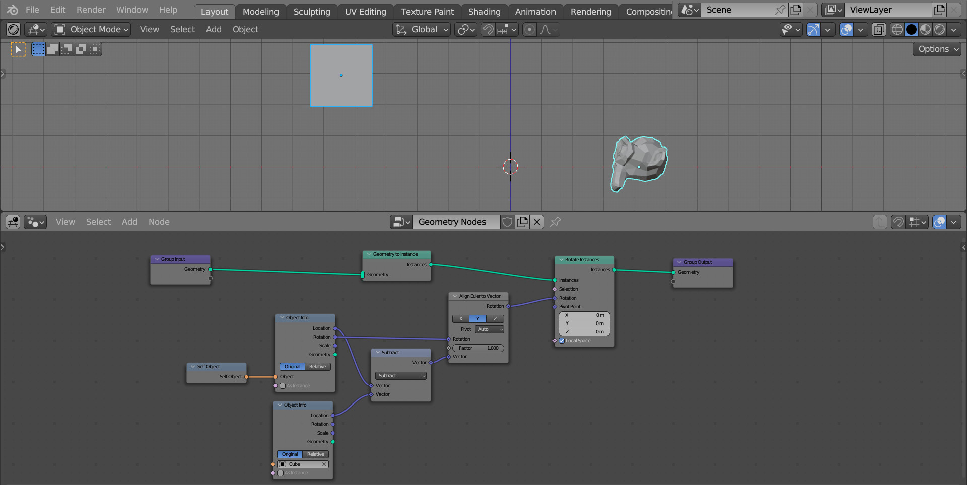
Now wherever we move Suzanne or the cube, Suzanne will always look at the cube.