Creating separate elements of procedural textures in Blender is quite simply – find the desired formula, rebuilt it using mathematical nodes, and as a result, get the desired shape. However, textures created this way have one feature – no tiling. Tiling – a cyclic texture duplication, most time is considered harmful, and professional 3D artists try to avoid texture tiling. But sometimes tiling is necessary, for example, when creating patterns or ornaments.
The procedural texture element is always created in a single instance. This is because all the mathematics that forms the actual procedural image is based on the initial data – coordinates that start from 0, spread out to infinity and not repeat. However, the same mathematics helps us to solve this problem.
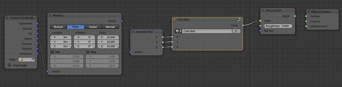
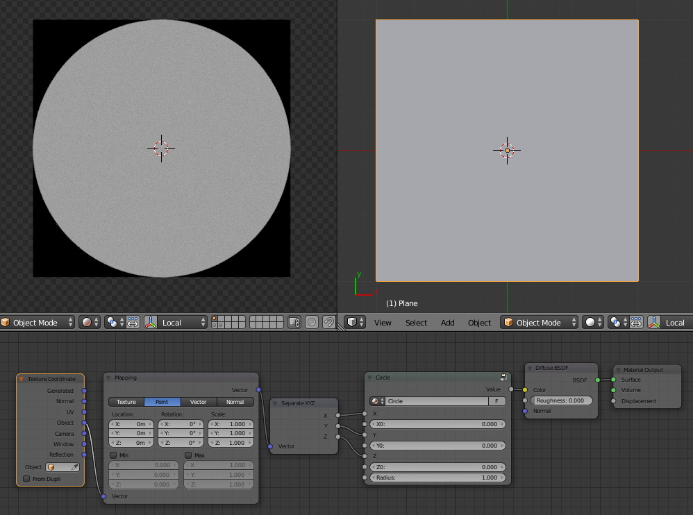
As an example let’s take the procedural circle texture. Create an experimental scene with the single plane. Assign the material that generates a procedural circle texture with a radius of 1 in the origin to this plane.
Reduce the overall texture scale by 10 times using the “Mapping” node with setting all its three “Scale” values to 10.
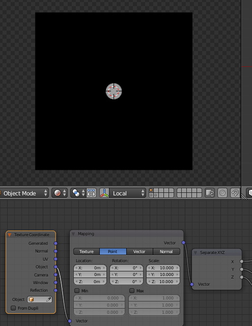
As we can see the circle does not tile and remains in a single instance in the center of the plane. Why is this happens?
Let’s return to the original formula, the base of our circle texture:
![]()
This function depends on three coordinates X, Y and Z, whose values start at 0 and are constantly increasing. All the resulting values of the left side of the formula are limited by the specified radius. The equal and smaller – used to draw the texture, larger – discarded.
We have limited the circle radius to 1. Therefore, the X, Y, and Z coordinates are limited to the range from -1 to 1.
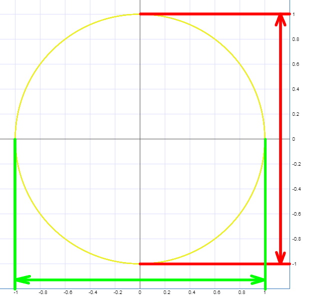
Let’s trace the X coordinate values starting from zero. 0, 0.1, 0.2 … – we are inside the circle, these coordinates are used for calculation. 0.3, 0.4 … 0.9, 1 – we are still inside the circle. 1.1 – this is not the circle range, we have gone beyond. 1.2, 1.3 … – we are still outside the circle, these values do not give us anything. But…
What happens if instead of the number 1.1 we again sent the value of 0.1 to the formula? Instead of 1.2, we sent 0.2, and so on? Can we take the coordinates range needed for the circle drawing and replace the current range, that no longer used, to it?

The current range [1,2] but with starting range [0,1] values given to the formula lets us stay in the radius limitation. And more, the next range [2,3] with a starting range [0,1] values gives us the proper result. And so on and so off.
To do this trick we can use the mathematical operation “remainder from integer division”, usually referred as “Mod”. It works as follows: for two numbers A and B, all whole B of A are discarded and the remainder returns as the result. For example:
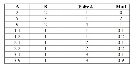
If we set the base value of the “Mod” operation equal to 1, we will receive a constant range of values from 0 to 1 through the all coordinate axis.
Let’s realize this with nodes.
Add new “Math” node
shift+a – Convertor – Math
and switch it to the “Modulo” mode. Insert it between the “Separate XYZ” node and the “Circle” node group. Connect the “X” output of the “Separate XYZ” node to the upper input of the “Modulo” node. Set the lower input value of the “Modulo” node to 1. Connect the “Value” output to the “X” input of the “Circle” group.
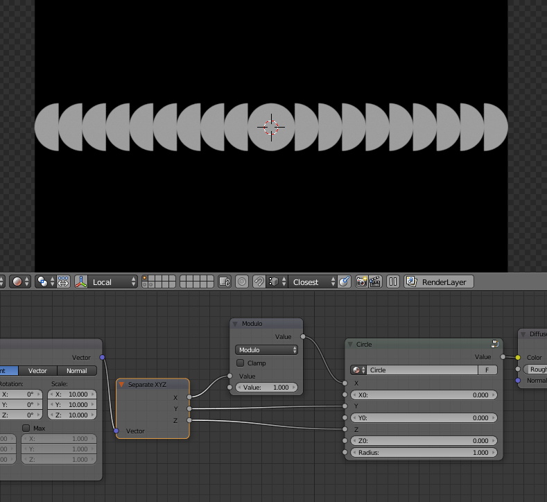
Add two more “Modulo” nodes for the Y and Z coordinates.
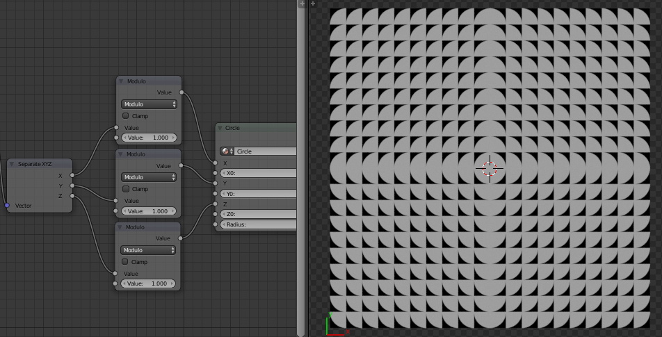
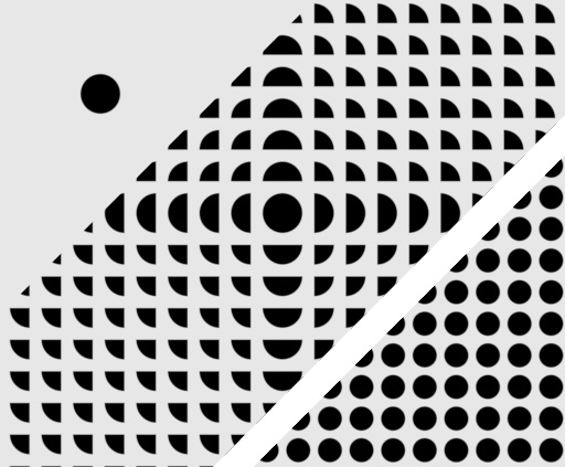
Now we have the texture tiling but a little bit wrong. This is due because the circle coordinates range from -1 to 1 and the “Modulo” tile values range from 0 to 1.
To draw the whole circle in the tile range, we need to reduce the circle radius and shift its origin. Set the “Radius” value to 0.5 and the origin coordinate values X0, Y0 and Z0 to 0.5.
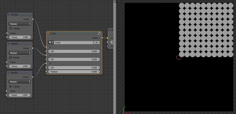
To modify the circle size and position we can change the values in “Modulo” nodes and the circle properties in the “Circle” group, but it’s easier to regulate it through the “Mapping” node.
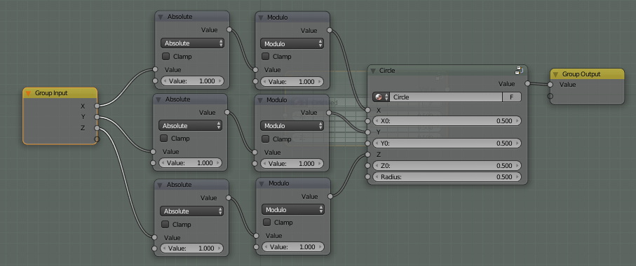
As we can see, the circle texture is tiled, but only in the positive direction of the coordinate axes. To tile it in the negative directions too, add three new “Math” nodes switched to the “Absolute” mode. In the “Absolute” mode the node converts the value from its upper input to the non-negative value without regard to its sign. Place them before each “Modulo” node. Connect the X, Y, Z outputs of the “Separate XYZ” node to the upper inputs of these nodes. Connect “Absolute” nodes outputs with the upper inputs of “Modulo” nodes.
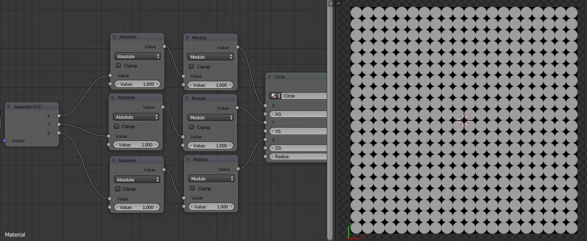
Now our procedural texture with a circle tiles right in all directions.
You can group all nodes for later use.