In order to achieve the desired texture mapping on the object surface, we need a convenient tool for manipulating the texture coordinates. Especially for procedural textures mapped to the object without using UV-s.
The “Mapping” node combines tools for texture moving, rotating and scaling is suitable for most of the texturing tasks. But sometimes its power is not enough. Its major drawback is that it allows setting adjustment values only in certain fields within the node body. These fields have no inputs and cannot be connected to the other nodes.
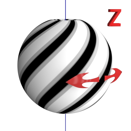
However, we can implement the required functionality devoid of the “Mapping” node lack with the help of some other nodes. Let’s consider how to build a node tree to rotate the texture around the Z-axis of the object by a random value.
- Prepare the scene:
- Add a sphere, assign the “Subdivision Surface” modifier to it and switch the polygon display to the “Smooth” mode in the T-panel.
- Switch to the “top” view. Now the sphere Z-axis is perpendicular to the monitor.
- Assign the default material (Diffuse 0.8) to the sphere.
- In the “Node Editor” window let’s start to create the required node tree:
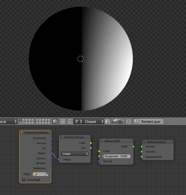
- Add the “Gradient Texture” node and connect its “Color” output to the “Color” input of the “Diffuse” node.
- Add the “Texture Coordinate” node, and connect its “Object” output to the “Vector” input of the “Gradient Texture” node.
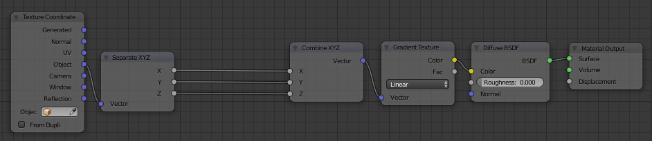
Now we have the following workpiece for our research:
So, we need to rotate the gradient texture around the sphere Z-axis.
We set the “Object” coordinate system of the sphere to the “Gradient Texture”. Therefore, the origin point for the texture calculation coincides with the origin point of the sphere, and the vector from the origin point to any point of the sphere surface is the vector that determines the texture color at that point.
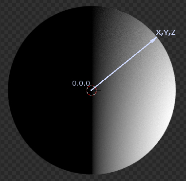
This means that in order to rotate the texture around the sphere Z-axis, we need to rotate all the vectors (0,0,0 – X,Y,Z) that we get from the “Object” output of the “Texture Coordinate” node around the origin point (0,0,0).
The matrix transformation is the best way to manipulate vectors in space. Not diving into the theory deep, the basic matrix transformation principle is: if a vector with known space coordinates is multiplied by a certain matrix, this vector is translated, rotated or scaled in a result.
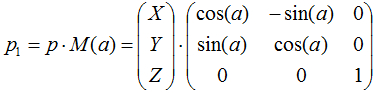
The Z-axis rotation matrix in three-dimensional space is the following:
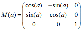
a – the rotation angle in radians.
Source vector:

we get from the “Object” output of the “Texture Coordinate” node.
In order to rotate this vector, we need to multiply it by the matrix:
According to the rules of multiplying a vector by a matrix, we obtain the following result:
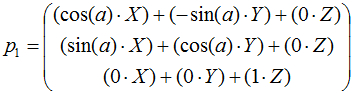
And with a little simplifying:
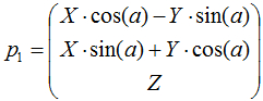
Having received the desired formula, we can put aside the mathematics manual and return to the Blender.
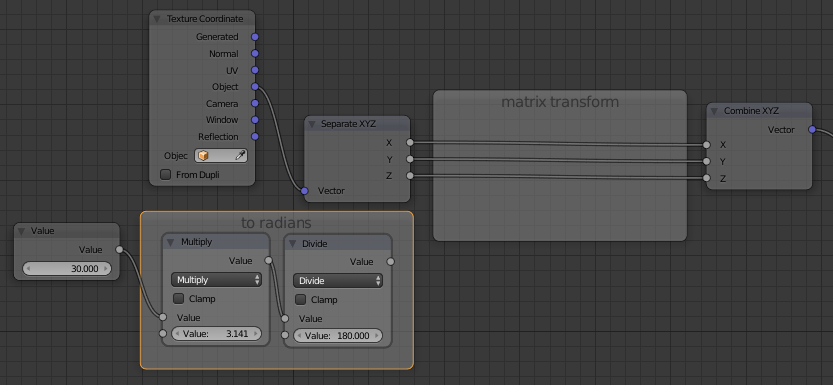
To access the coordinates of the source vector p(X,Y,Z) separately, let’s add a new “Separate XYZ” node to the node tree. This node allows dividing a vector into its coordinate components. Since after the transformations we need an entire vector again (for the “Vector” input of the “Gradient Texture” node), let’s also add the “Combine XYZ” node, which allows us to compile a vector from the components.
After connecting the corresponding node’s inputs and outputs, we obtain the following tree:
We will build all the “math” between the “Separate XYZ” and “Combine XYZ” nodes.
Let’s add a new “Value” node. This node will establish the a variable value – the rotation angle in degrees. But our transformation formula requires an angle in radians. So we will convert degrees to radians by multiplying the value by π and dividing it by 180 with two “Math” nodes.
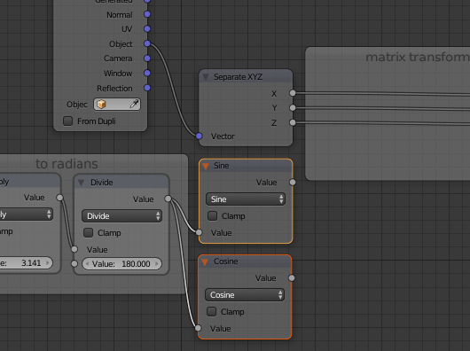
In our transformation formula, the rotation angle is not used as is, only its sine and the cosine are needed. Add another two “Math” nodes to get the sine and cosine.
It remains to perform mathematical calculations for each vector coordinate.
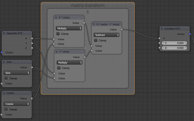
For the X-coordinate: add two “Math” nodes (Multiply) to obtain the products X*cos(a) and Y*sin(a), and the third “Math” node for subtraction of the second product from the first. As a result, we realized the formula X*cos(a)-Y*sin(a).
Let’s realize the Y-coordinate formula in the same way:

The Z-coordinate value does not change, so simply connect the corresponding input and output of the “Separate XYZ” node and the “Combine XYZ” node.
The resulting node tree looks like this:
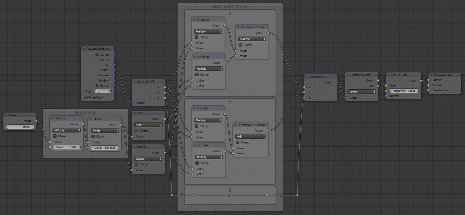
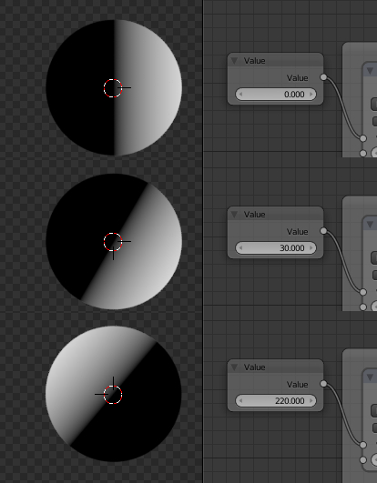
Сhanging the “Value” node value, we can observe how the texture rotates.
But we just could get this result only with the single “Mapping” node. Let’s rotate the texture to a random angle.
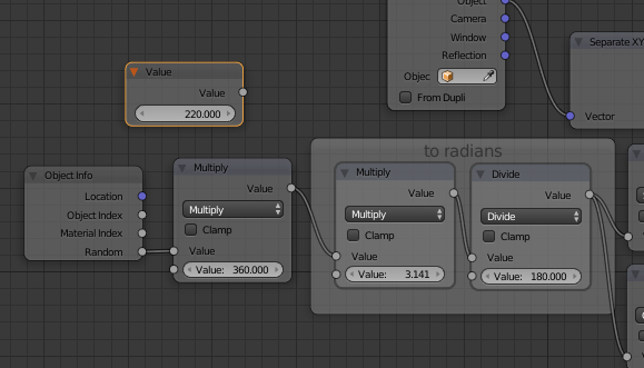
To do this, detach the “Value” node from the rotation angle determination. Add the “Object Info” node. This node has the “Random” output that generates a random value in the range from 0 to 1. But the rotation angle changes from 0 to 360 degrees. So, add another “Math” node multiplying the value taken from the “Random” output by 360. Connect nodes to determine the rotation angle a.
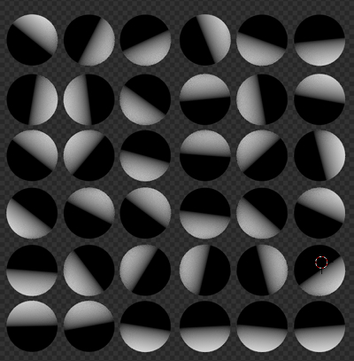
And now let’s create several more spheres, assigning all of them the material with the created node tree.
This is an amazing tutorial, which I have already ported over to Terragen, as it’s something I desperately needed there too. I would be super appreciative if you could dive into a scaling matrix that can scale textures via a node formula.
There is no problem with scaling – it’s just a multiplying vector by value.