To create radial arrays – the arrangement of objects along a circular path, the “Array” modifier is usually used in Blender. However, such an array can be easily made using Blender Geometry Nodes.
 .blend file on Patreon
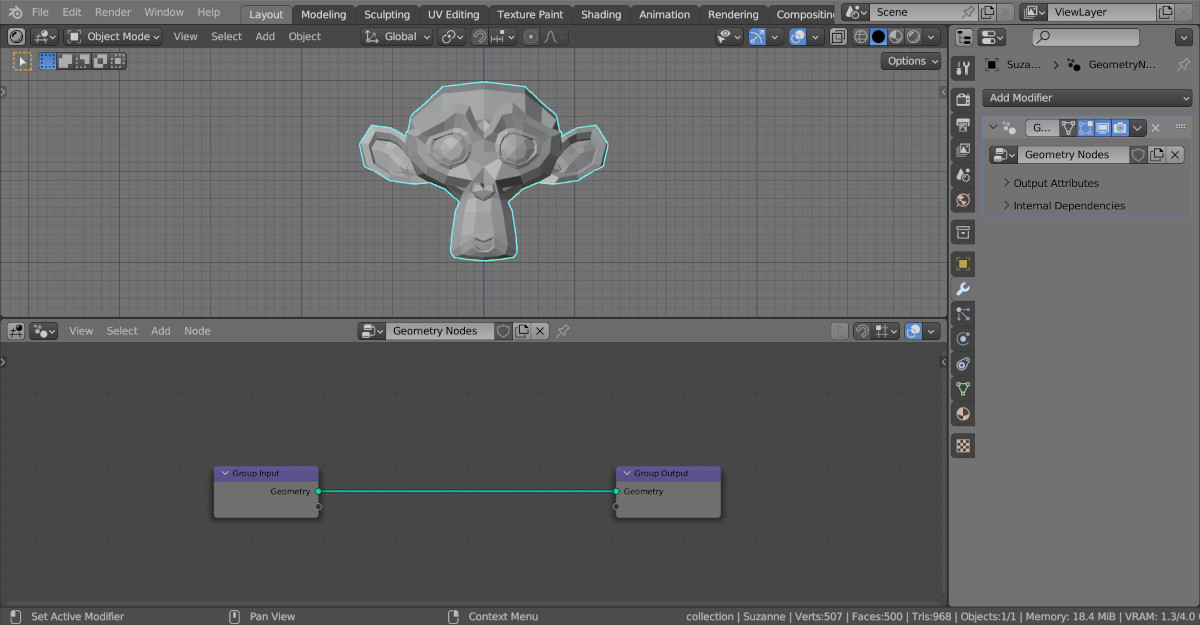
Let’s add an object to the scene that needs to be arranged along a circular path, for example, Suzanne (shift + a – Mesh – Monkey). Assign the Geometry Nodes modifier to it and create the initial node tree by clicking on the “New” button.
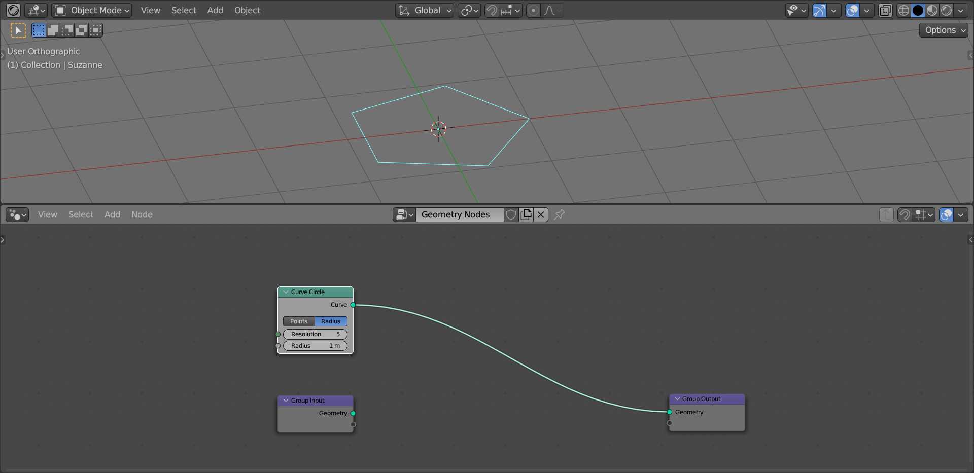
Add a circle curve (shift + a – Curve – Primitives – Curve Circle), at the points of which we will later place the mesh instances. In its “Resolution” parameter, set the number of future objects placed in a circle, for example, 5.
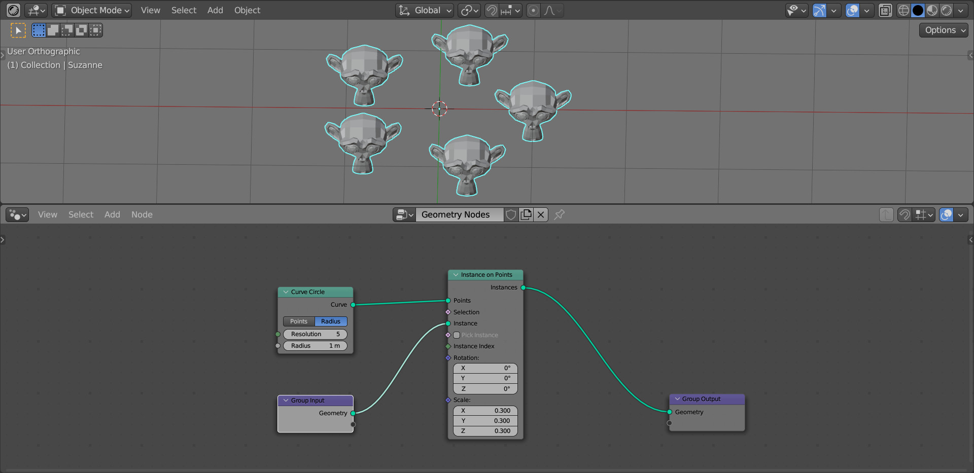
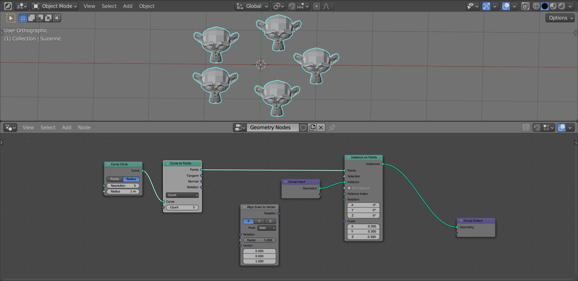
To place an instance of Suzanne at each point of the curve, add an Instance on Points node (shift + a – Instances – Instance on Points). Link its “Points” input with the “Curve” output of the Curve Circle node, and its “Instance” input with the “Geometry” output of the Geometry Input node, which is responsible for the initial geometry of the mesh.
As we can see, now an instance of the initial mesh is placed at each point of the curve. Scale of instances can be adjusted by changing the value in the “Scale” field of the Instance on Points node.
The mesh is placed in a circle, but its direction of view remains the initial.
We can orient the mesh so that it faces the center of the circle using the Align Euler to Vector node (shift + a – Utilities – Rotation – Align Euler to Vector). This node allows rotating one of the object’s axes so that it looks along the given axis.
We need to rotate Suzanne so that her direction of view, the Y-axis, sees along the normal of our circular curve.
We can get the normal to any curve point using the Curve to Points node (shift + a – Curve – Operators – Curve to Points). Add this node to the node tree right after the Curve Circle node.
Please note that the “Count” parameter must be set to the same value that we set in the “Resolution” parameter of the Curve Circle node – 5, so that no additional points are appeared.
Nothing has changed in the construction of the radial array, but now we can get the normal to the curve from the “Normal” output of the Curve to Points node.
Link this output to the “Vector” input of the Align Euler to Vector node, and link the “Rotation” output of this node with the “Rotation” input of the Instance on Points node.
In the Align Euler to Vector node parameters, set the Y axis to apply.
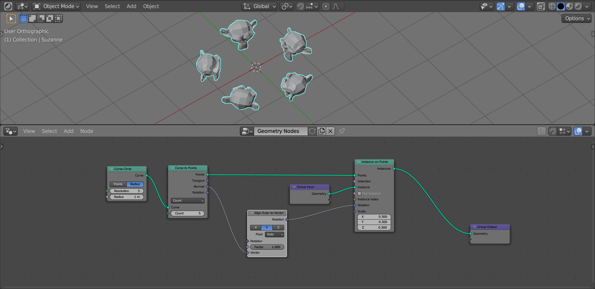
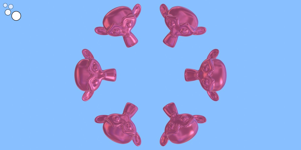
Now all Suzannes “look” the way we need.