Creating thin long objects like pipes and wires is the often task in the interior, scientific of fantastic scenes. One of the easiest and most convenient ways to create such objects is using curves.
The main curves advantage is the easiest control and editing: any time you can change the shape of the curve, move its points, add new and delete unnecessary ones. You do not have to work with a lot of mesh points, but only with several points of the curve, which is much more convenient. Preprocessing for rendering scene with curves is also performed faster than with meshes.
Simple wires
- Let’s add a curve to the scene:
- shift + a – Curve – Bezier
- Switch to the editing mode (TAB) and shape the curve, moving, rotating and scaling its points.
- Move point: g
- Rotate: r
- Extruding new points from the end of the curve: select the point at the end – e
- Insert some points between two others: select two points – w – subdivide
- Removing a point or segment of a curve: x or del
- Duplication of points and segments: shift + d
- Connect two points: f
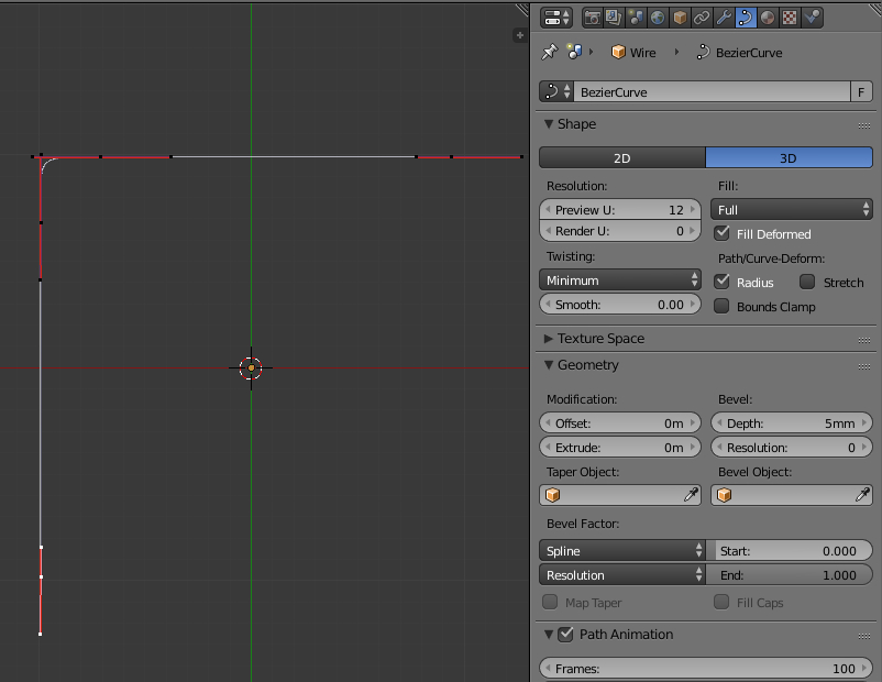
- It remains to make the curve volume:
- In the Properties window in Object Data tab set:
- in the Shape panel:
- Fill – set to “Full”
- in the Geometry panel:
- Bevel
- Depth = 0.005 – This parameter adds volume.
- In this panel, it is possible to raise the value of the Resolution parameter, which responsible for the final grid density – how smoothly the curve looks. But instead, it’s easier and more convenient to switch to the modifiers tab, add the Subdivision Surface modifier and control the curve smoothing through it.
- Bevel
- in the Shape panel:
- In the Properties window in Object Data tab set:
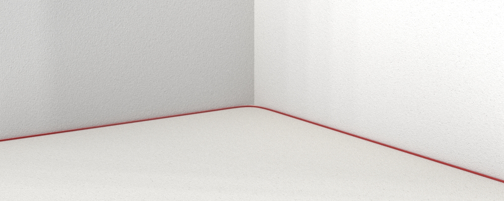
After assigning a suitable material to the curve, we obtain the finished wire:
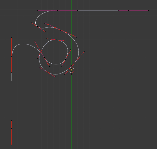
- And now let’s see how easy its managing is:
- Select two points forming the angle of the wire
- w – Subdivide – in T-panel set the number of cuts equal to 8
- And just move and rotate that additional points:
- Select two points forming the angle of the wire
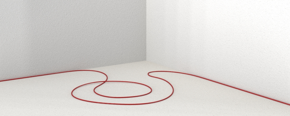
After these simple manipulations the wire began to look much more interesting:
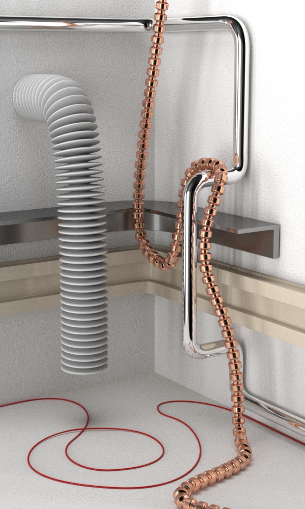
Pipes
Pipes are the same wires, just with a large diameter. All the advantages of modeling with curves are preserved.
- Add one more curve to the scene.
- Set it to the required position by adding and moving points.
- Set the volume:
- Shape – Fill = Full
- Geometry – Bevel – Depth = 0.05.
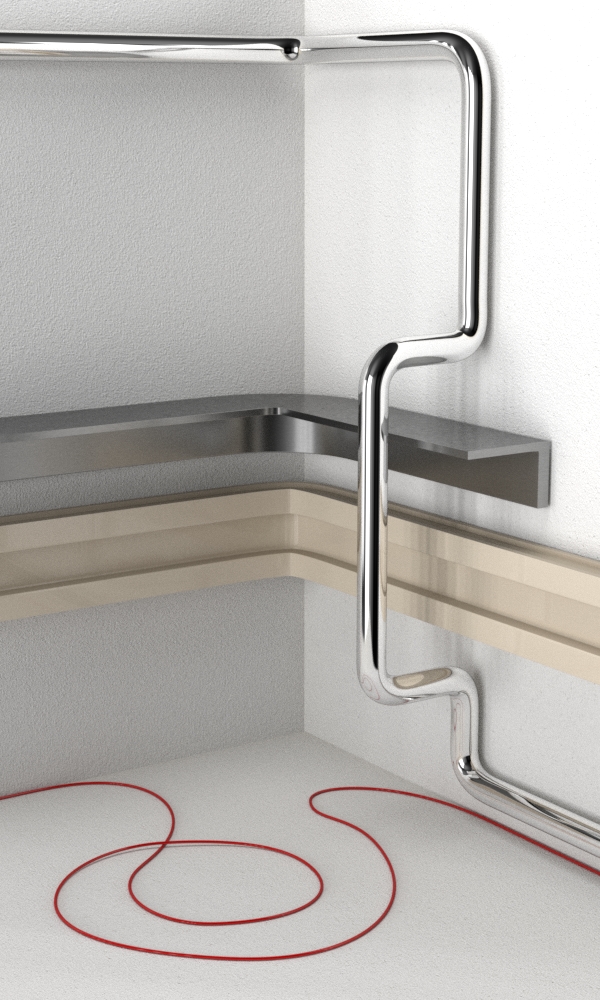
- And assign a suitable material, for example, chromium-plated metal:
 Various profiles
Pipes and wires have a circular profile, which can be easily set by adjusting the Bevel – Depth parameter. However, some times it is necessary to model long objects having an arbitrary profile. For example – a plinth, a wire box, rails, beams and many other. Is it possible to use the flexibility of modeling such objects with curves?
We must use two curves to obtain the arbitrary profile. The first curve is the path. Like pipes modeling, the final object will stretch along it. The second curve is the profile. It specifies the shape of the final object profile.
- Let’s add two curves to the scene.
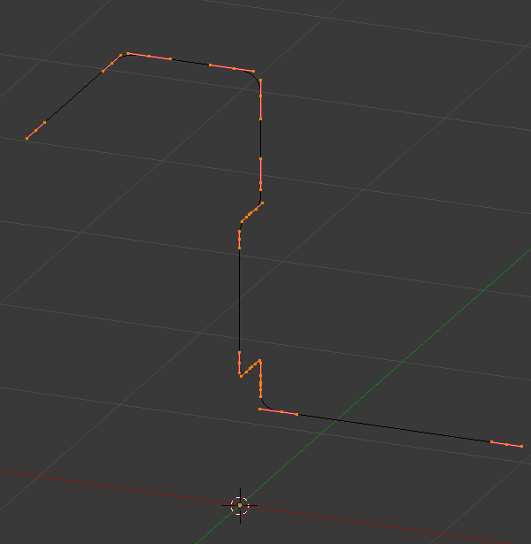
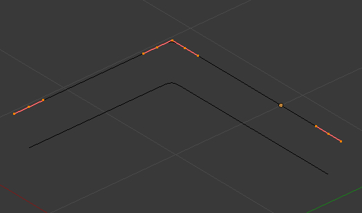
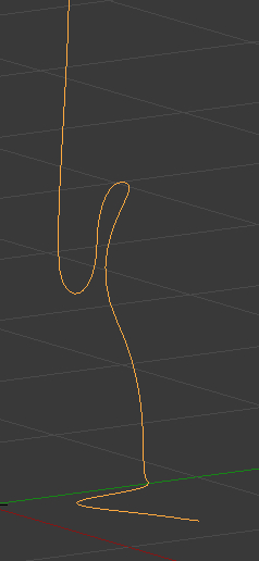
- Set their shape and location to make two paths.
- Add Subdivision Surface modifier to them for smoothing.
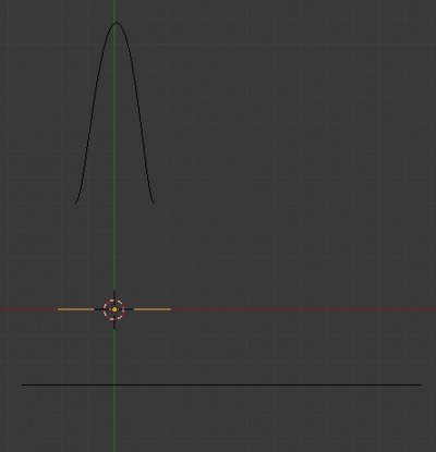
- Add to the scene a curve to create a profile of the “corner” shape.
- Name it “Profile1”.
- Edit its shape to form necessary profile.
- To make a right angle change the point type:
- Select the desired point – v – Free
- Now the control points can be moved independently of each other.
- Pay the particular attention to the origin location. The origin point slides along the path curve when making an object. Other points move relative to the origin.
- Reduce curve size a bit – the final object will match the size of the profile curve.

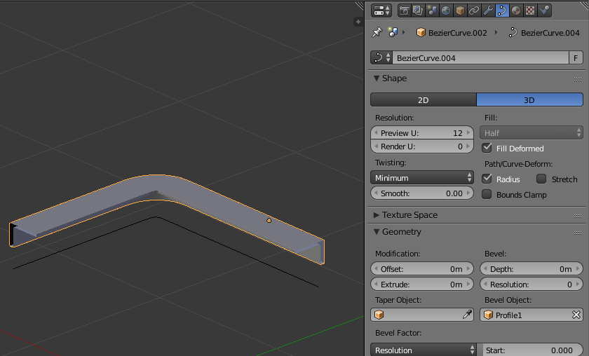
- Select the first path curve.
- In the Properties window in Object Data tab set
- in the Geometry panel in the Bevel Object field
- Specify created profile curve “Profile1”
- in the Geometry panel in the Bevel Object field
- On the Fill Caps checkbox in the Geometry panel – the ends of the object will be filled.
- In the Properties window in Object Data tab set
- Add another curve to the scene to create a profile of the “box” shape.
- Name it “Profile2”.
- As for the first profile, form the desired shape relative to the origin adjust curve size.

- Select the second path curve and specify the “Profile2” curve in its Bevel Object field.

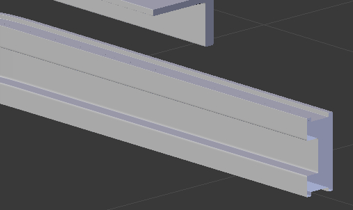
- Let’s make sure of the wonderful flexibility of our modeling method again – make a notch on the surface of our “box”. The “box”, created as mesh, needs to manually extrude a series of points along all the surface. In our case we only need to:
- Select the profile curve (“Profile2”) and change its shape in the edit mode:

All changes are immediately transferred to the final “box”:
- Let’s assign materials to the created objects:
Ribs and variable diameter
All the objects we created above have the same thickness along the entire length. But what should we do to model a pipe with a variable diameter? It’s also possible with curves.
- At first, add a path curve to the scene and set its shape.
- Add another curve to the scene. It will be responsible for changing the diameter over a certain segment.
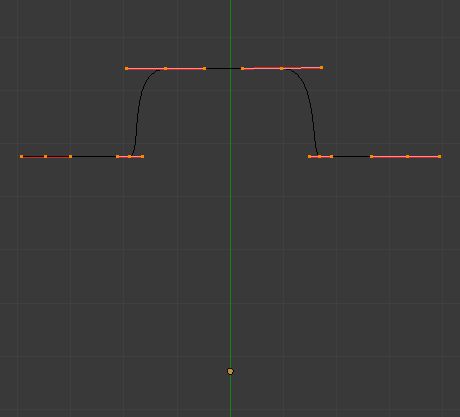
- Name it “Taper”.
- Here again, pay attention to the curve points placement relative to the origin point. The distance between each point and the origin point determines the diameter in a certain place of a pipe.
- Add one more curve to the scene, which will consist of only two points connected by a straight line segment. We will create the final object from this curve.
- Set the diameter to that curve:
- Bevel – Depth = 0.01
- Add the Subdivision Surface modifier to the curve for smoothing.
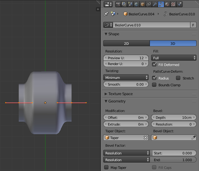
- In the Geometry panel:
- In the Taper Object field specify the curve “Taper”.
- Set the diameter to that curve:
Now we got a pipe section with a variable diameter. It remains to reproduce it along the path.
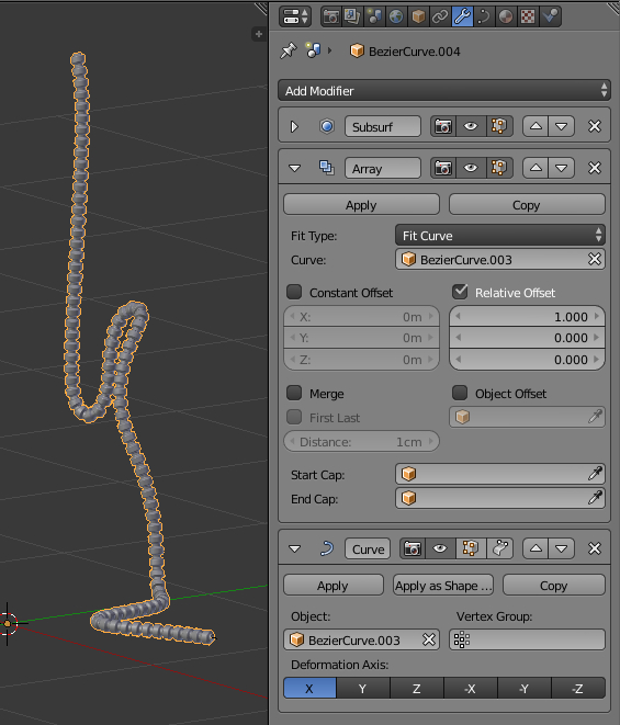
- In the Modifiers tab:
- Add an Array modifier to the curve and set the parameters:
- Fit Type = Fit Curve,
- Curve – specify the path curve.
- Add Curve modifier
- In the Object field – specify the path curve.
- Add an Array modifier to the curve and set the parameters:
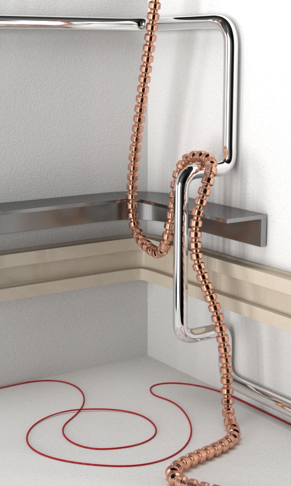
Assign the material to the pipe.
Filling path or a constant number of ribs?
There are two cases in constructing pipes with a variable diameter:
- As in the example above, the whole trajectory of the path is filled with constant length segments. The number of segments is not known in advance, but this method will always ensure filling the whole path length. If we need to increase the pipe length, we simply increase the path curve length and additional segments will be automatically added.
Let’s see, how it works while extruding one end point of the path curve:
- In the second case, a typical example of which is a corrugated pipe, the number of segments per pipe length should remain constant. When stretching the pipe, the segments must also be stretched.
- Let’s create, as in the example above, 3 curves:
- The path curve with “Path2” name,
- Pipe segment base with “Segment2” name,
- And the diameter change curve with “Taper2” name.
- Make the pipe from the “Segment2” curve:
- Set the pipe diameter with the parameter:
- Bevel – Depth = 0.2
- Specify the “Taper2” curve in the Taper Object field to make our pipe the variable diameter.
- Scale the segment along its axis a bit, to look like a classic corrugated pipe segment.
- Add Subdivision Surface modifier.
- Add Array modifier and set parameters to:
- Fit Type = Fixed Count
- Count = 30
- And Curve modifier and specify the path curve “Path2” in the Object field.
- Set the pipe diameter with the parameter:
- Select the “Path2” curve:
- In the Properties window in the Object Data tab in the Shape panel on two check boxes:
- Stretch
- Bounds Clamp
- In the Properties window in the Object Data tab in the Shape panel on two check boxes:
- Let’s create, as in the example above, 3 curves:


Now, if we move or extrude the path curve points new segments are not added and the existing ones deform according to the curve length change:
It remains to arrange the path curve in the right way and assign the material to the pipe.