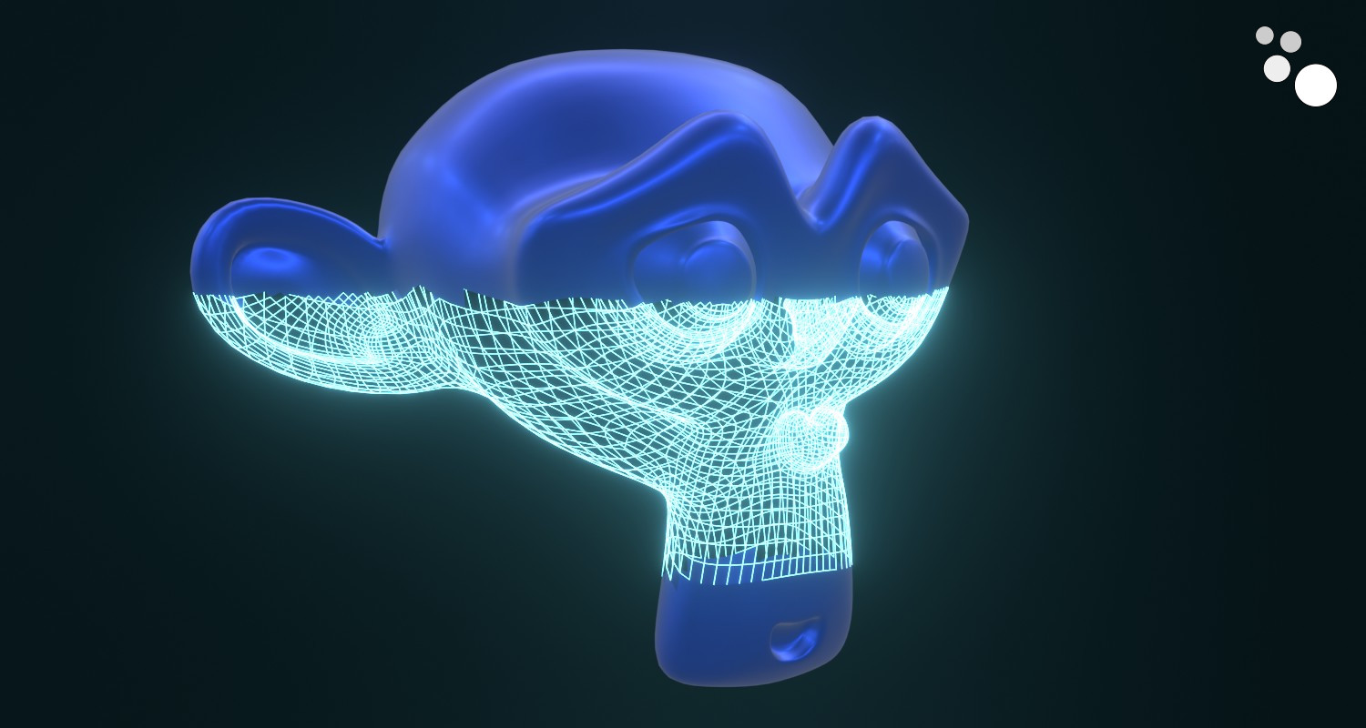
A simple but effective way to visualize an object laser scanning in a sci-fi style can be done in Blender using Geometry Nodes.
 .blend file on Patreon
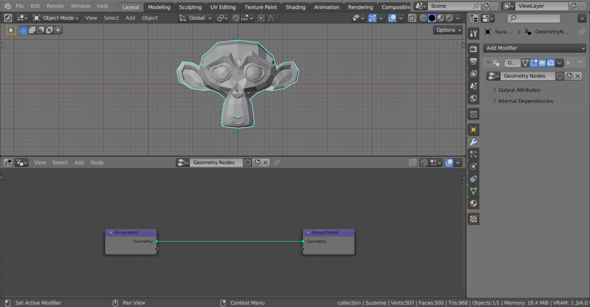
Let’s take Suzanne and add her to the scene (shift + a – Mesh – Monkey), append a Geometry Nodes modifier and create an initial tree of nodes by clicking on the “New” button.
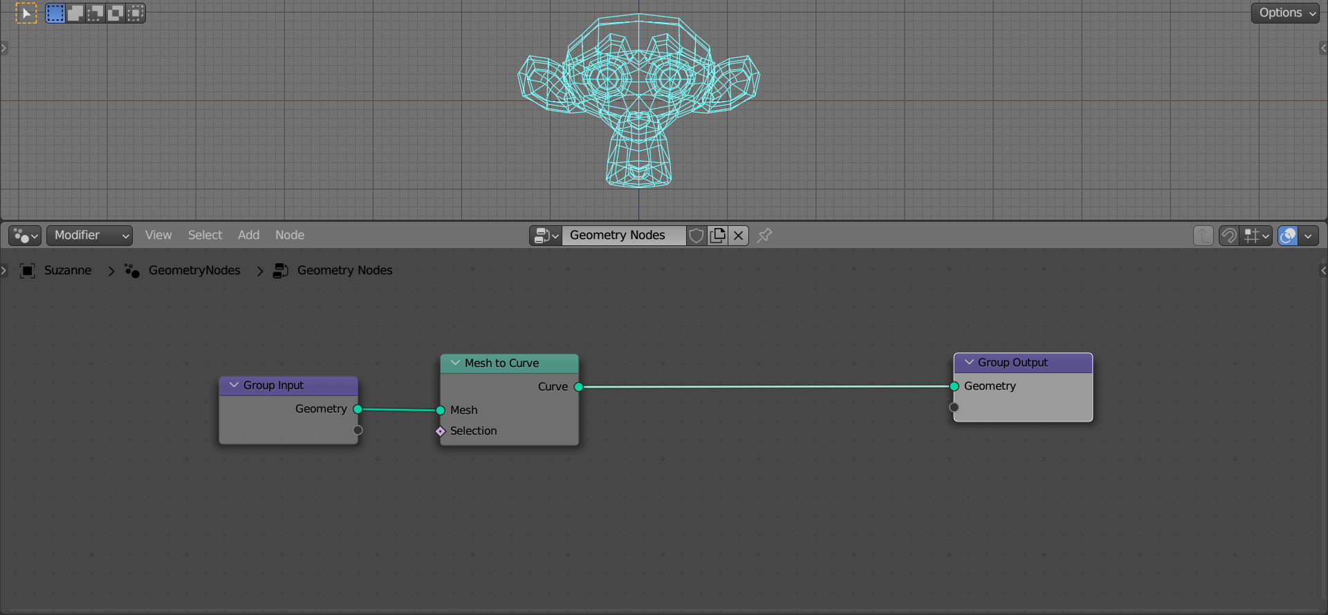
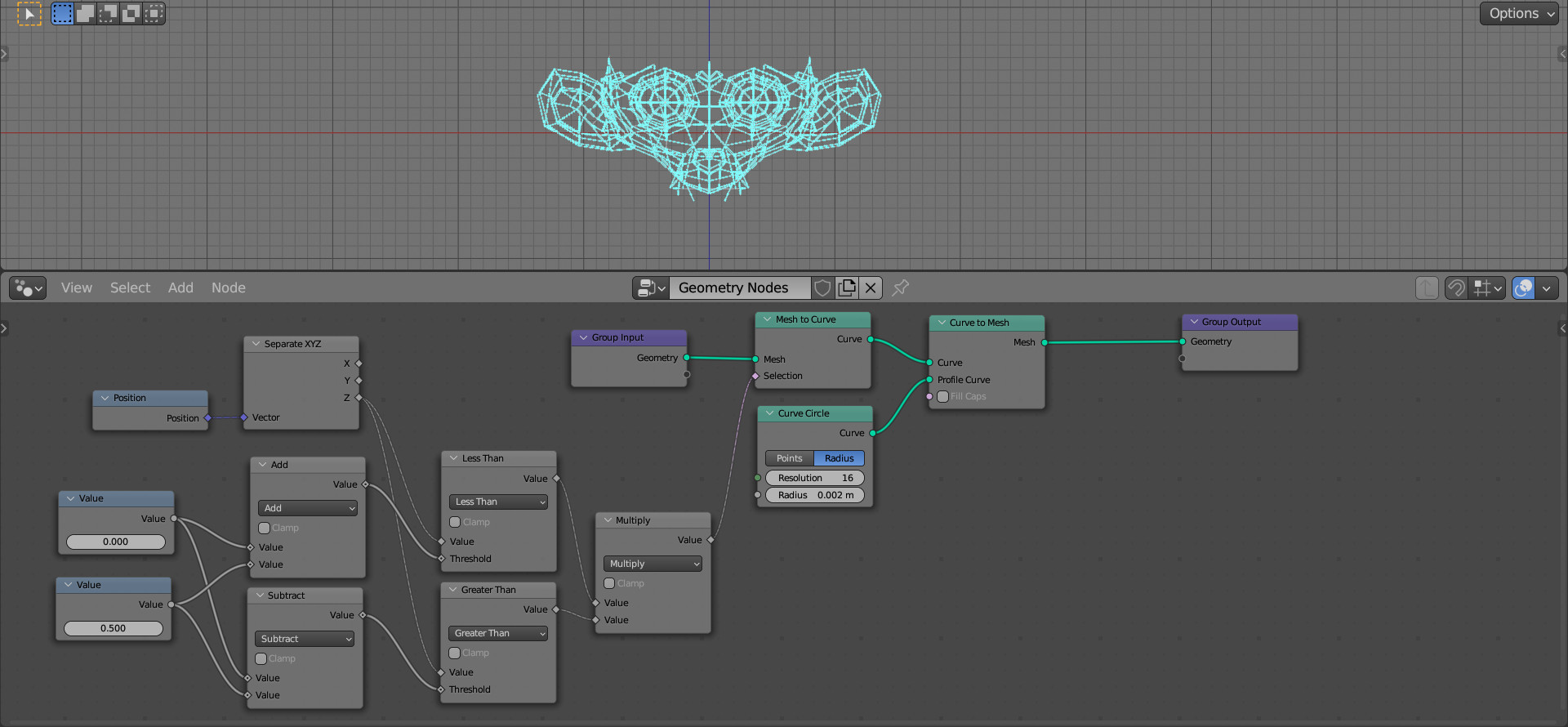
To convert the mesh into lines, with which we will simulate laser scanning, add the Mesh to Curve node to the main branch of the node tree (shift + a – Mesh – Operators – Mesh to Curve).
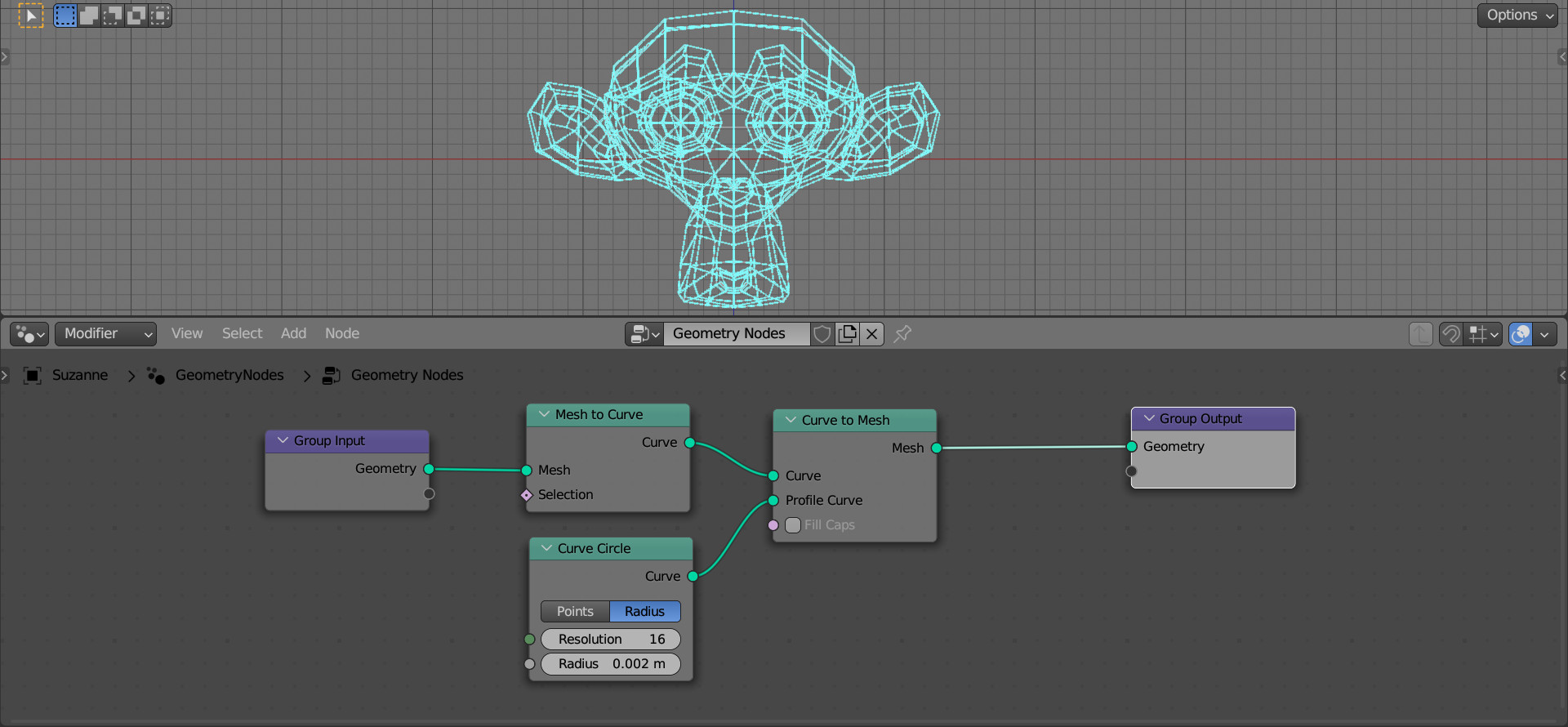
To add thickness to the resulting lines, we can make the reverse transformation to a mesh, using the Curve to Mesh node (shift + a – Curve – Operators – Curve to Mesh), placing it after the Mesh to Curve node.
Also add a Curve Circle node (shift + a – Curve – Primitives – Curve Circle) and link its Curve output with the Profile Curve input of the Curve to Mesh node. Set the following values: Resolution = 16 and Curve Radius = 0.002.
So far, we have all of Suzanne converted to a grid. Let’s make a height constraint, simulating a scan frame.
We will orient to the vertical position of the mesh points.
Add the Position node (shift + a – Geometry – Read – Position). We will take the position of the mesh points from it. Add a Separate XYZ node (shift + a – Utilities – Vector – Separate XYZ) and link its Vector input to the “Position” output of the Position node. We will select a Z-coordinate for each point of the mesh this way.
Now let’s define the range of values with which we will compare the resulting Z-coordinate. If it falls into the range – this is the scan area, if not – the base surface of the mesh.
Let’s add two input Value nodes (shift + a – Input – Constant – Value). The first will be responsible for the position of the scan frame, and the second – for its size. For the second node, set the Value to 0.5.
To create a range from two values, add two Math nodes (shift + a – Utilities – Math – Math). We will leave one in the “Add” mode, and switch the second to the “Subtract” mode. Connect the output of the first Value node to the upper inputs of the Math nodes, and the output of the second one to the lower ones.
To compare the Z-coordinates of the points with the resulting range, add two more Math nodes (shift + a – Utilities – Math – Math) and switch them to the “Less Than” and “Grater Than” modes. Link the “Z” output of the Separate XYZ node to the top inputs of these nodes. Connect the lower inputs to the outputs of the Add and Subtract nodes, respectively.
Add another Math node (shift + a – Utilities – Math – Math) and switch it to “Multiply” mode. Link outputs of the Less Than and Grater Than nodes to its inputs.
And the last step – will feed the result obtained at the output to the “Selection” input of the Mesh to Curve node.
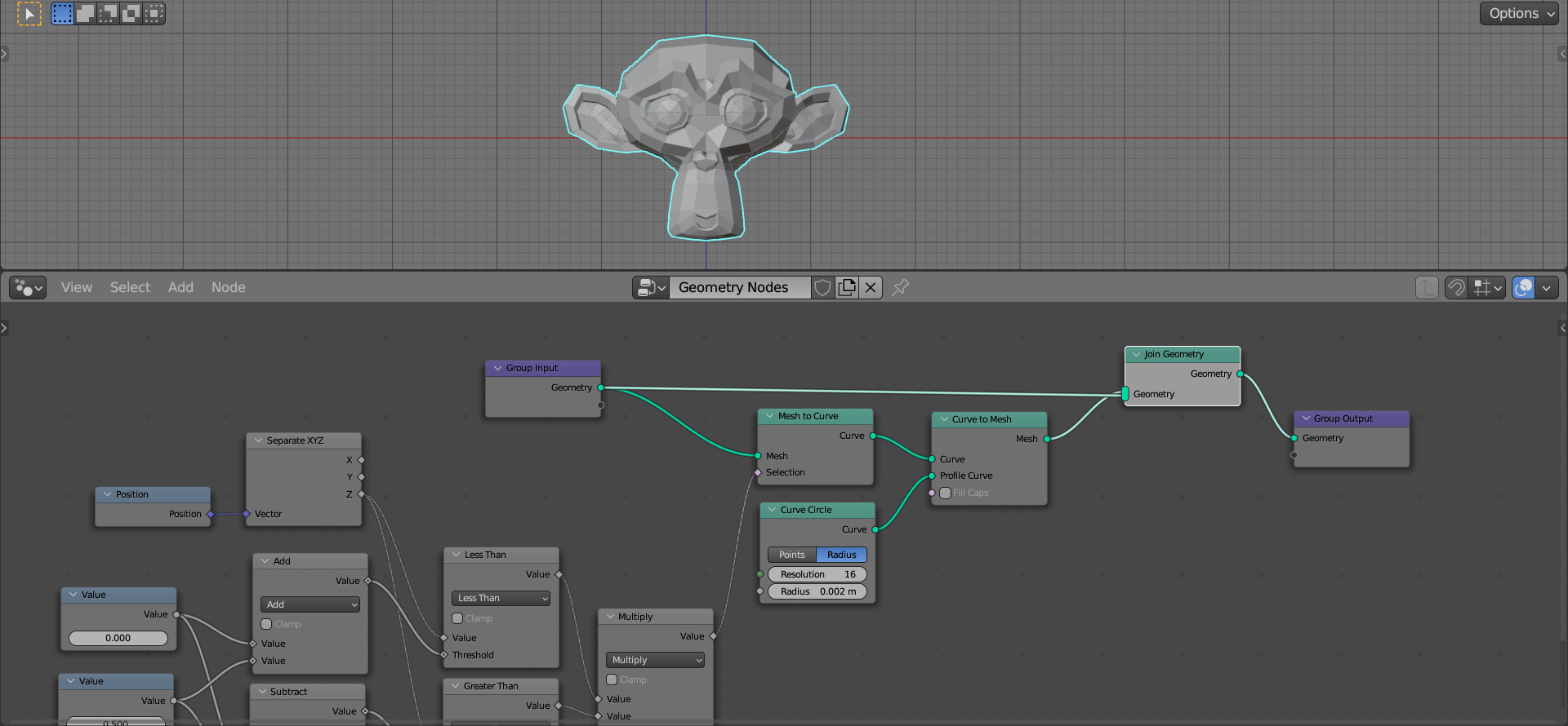
As a result, we see that only a part of the mesh was converted into lines, limited by the parameters we set in Value nodes.
For the rest of the mesh not to disappear, add the Join Geometry node to the end of the node tree (shift + a – Geometry – Join Geometry) and create an additional link to it from the starting Group Input node.
However, the original geometry in the scan area was also restored. Let’s remove it using the Delete Geometry node (shift + a – Geometry – Operators – Delete Geometry). To the “Selection” input of the Delete Geometry node, link the result of the range we have already calculated for the scan frame from the output of the Multiply node.
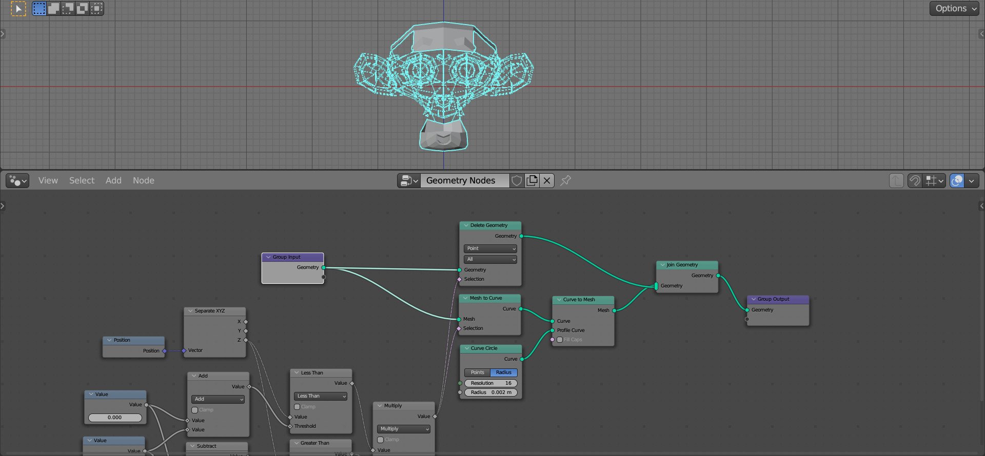
Now everything looks as it should.
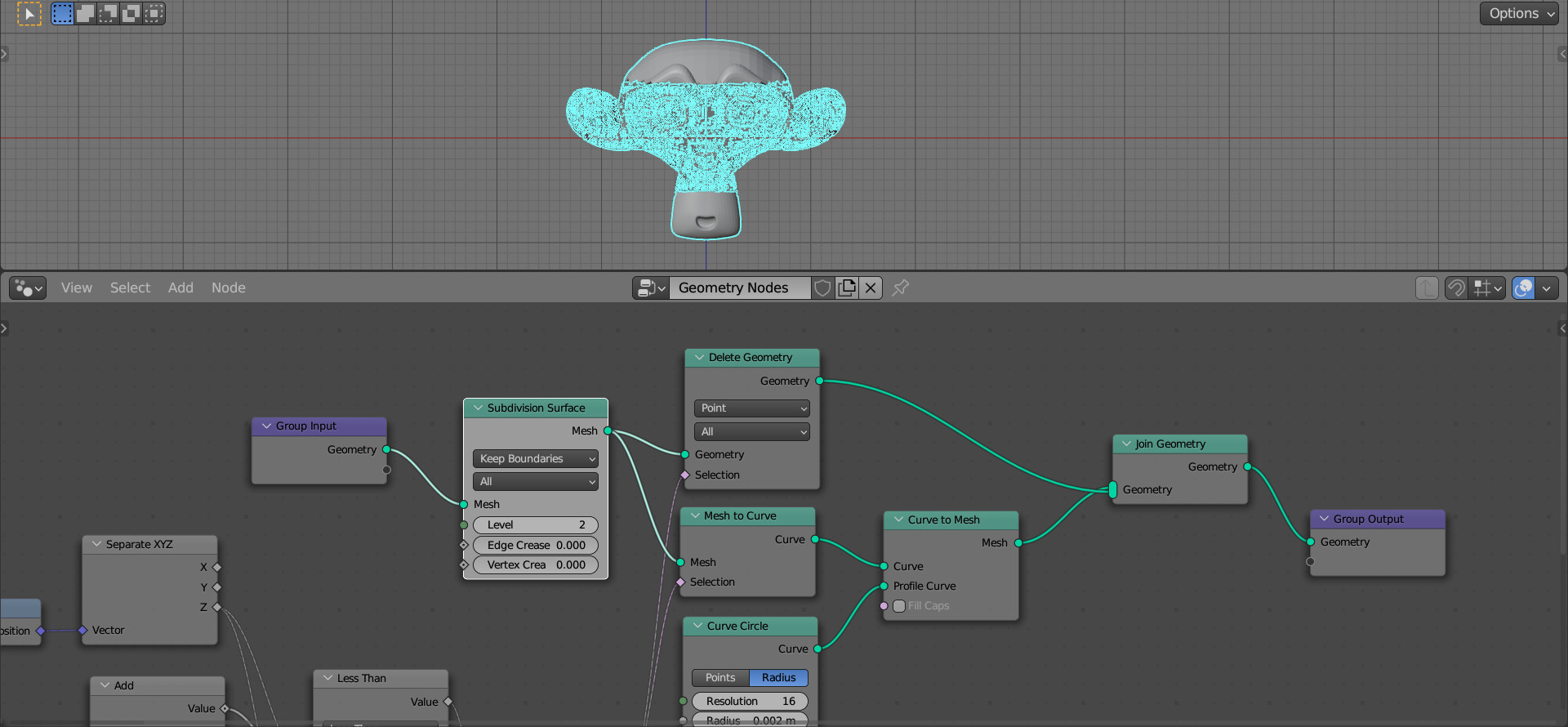
Let’s add a Subdivision Surface node (shift + a – Mesh – Operators – Subdivision Surface) to the very beginning of the node tree to increase the number of lines and make the border of the scanning frame more solid. Set the Level value to 2.
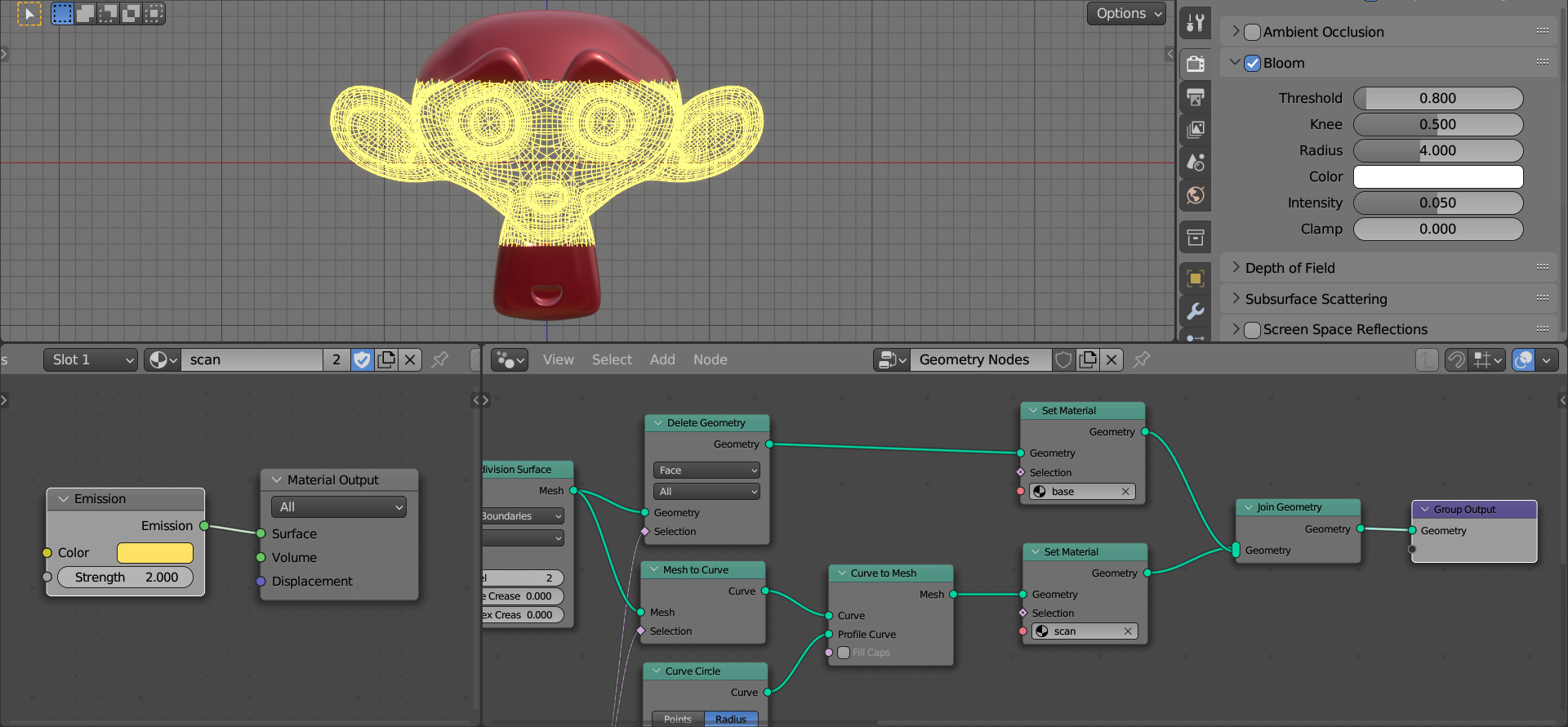
Assign different materials to the solid part of the mesh and to the scan area. Add two Set Material nodes (shift + a – Material – Set Material) to both branches of the node tree before the Join Geometry node. In the Shader Editor, create two different materials, for the solid part of the mesh and for the scan area, and specify these materials in the Set Material nodes.
For the material of the scan area, we can use the Emission shader, which will highlight the grid lines of the mesh. Also, if using the EEVEE render engine, we can turn on Bloom to create an aura of glow.
By animating the values in the Value nodes, we can get the scanning animation.