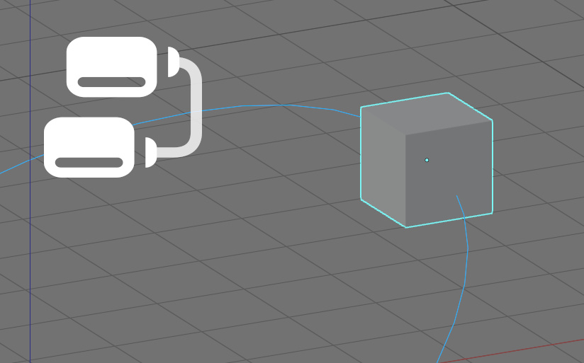
We can make a mesh move along a curve in Blender using Geometry Nodes. Let’s take a simple example of how to do this.
 Example .blend file on Patreon
Let’s add a cube and a curve to the scene
shift+a – mesh – cube
shift+a – curve – circle
set the radius to 10 in curve parameters.
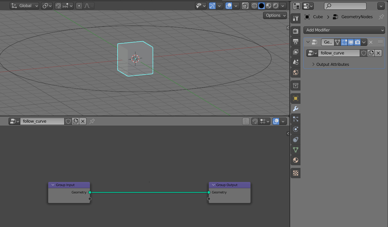
Select the cube, open its modifiers tab in the “Properties’ area and add a “Geometry Nodes” modifier to it. Name it “follow curve”.
To access the curve data inside the cube geometry nodes node tree, add the “Object Info” node and select “Bezier Circle” in its object field. Switch its mode to “Relative”. This is necessary to correctly align the cube with the curve if their “origin” points do not match.
We can get the coordinates of any point on the curve, to which we will place our cube, using the “Sample Curve” node. Let’s add this node and connect it to the “Object Info” node of the curve.
Switch its mode to “Factor”. Now the value in the “Factor” field gives us the relative position of any point on the curve, assuming the length of the entire curve is measured from 0 to 1.
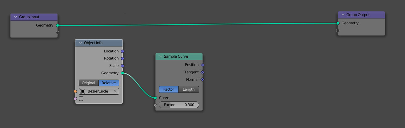
We can get the coordinates of a point on the curve from the “Position” output of the “Sample Curve” node.
Now we can shift all the points of our cube to the position obtained from the “Position” output, which will be the same as snapping the cube to that point on the curve.
Let’s add a “Set Position” node to the main nodes branch. Connect the “Position” output of the “Sample Curve” node to the “Offset” input of the “Set Position” node to shift all cube vertices to a point on the curve.
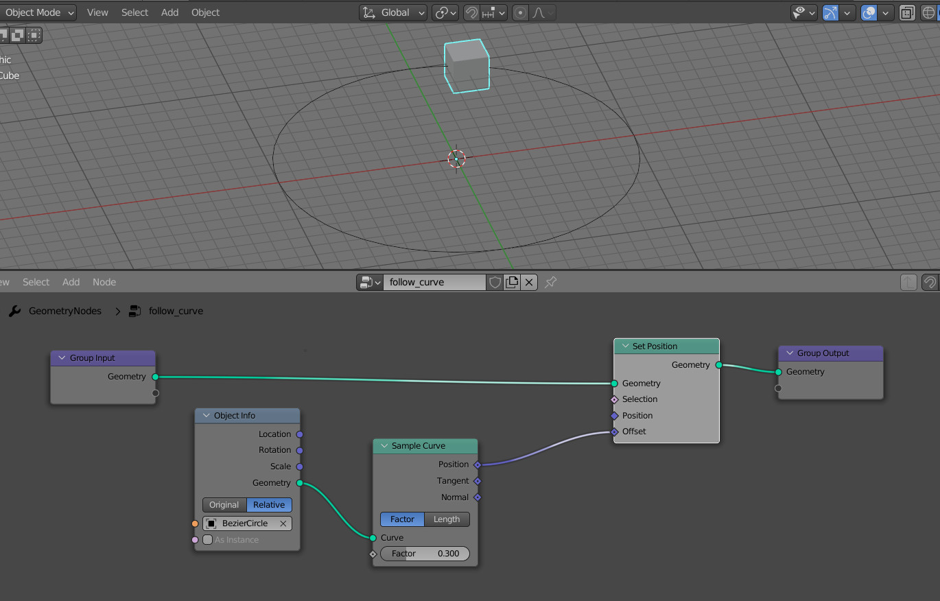
Now when we slide the “Factor” value of the “Sample Curve” node, the cube will move along the curve.
The goal is achieved, but we can see that the cube moves along the curve statically, without turning to the direction of movement.
To make the object tern to the motion direction, we can rotate its “X” axis along the curve tangent.
Let’s add an “Align Euler to Vector” node to the node tree and connect its “Vector” input with the “Tangent” output of the “Sample Curve” node. Set the rotation axis to “X”. So, the “X” vector of the cube will now align with the tangent vector at the current point on the curve.
To transfer this rotation to the cube, add a “Transform” node to the main branch of the tree and connect the “Rotation” output of the “Align Euler to Vector” node to its “Rotation” input.

Now the cube is always faced along the curve.
However, if the curve does not place in the initial coordinates, we can see that the cube not only rotates in the direction of motion but also begins to rotate around its axis.
To compensate for this rotation, we can additionally control the “Z” axis of the cube at the current point on the curve.
Let’s add another “Align Euler to Vector” node, link its “Vector” input with the “Normal” of the “Sample Curve” node and add this rotation to the existing one by connecting the “Rotation” inputs and outputs of both “Align Euler to Vector” nodes.
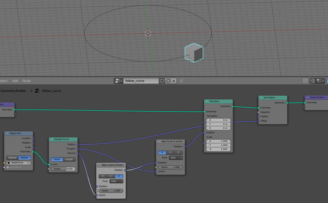
As a result, our cube moves along the curve, turning in the direction of movement and maintaining a vertical orientation along the normal of the curve.
thanks it is very helpfull
didn’t work. I got the node setup exactly the same
Can you attach your file?
didnt move
an image
I assume you used a mesh circle but not the curve.
didnt work for me.. version 3.01
Maybe you made a mistake with nodes? This way works in 3.0.1.
didnt move
Replied above.