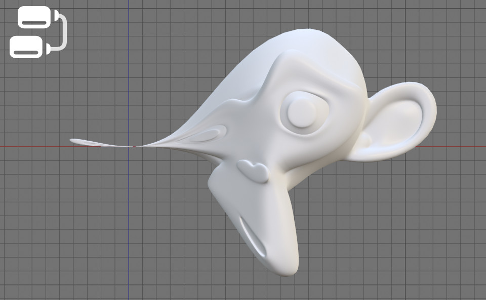
With Geometry Nodes in Blender we can easily create the effect of an object flowing from place to place. The effect is universal and can be applied to any mesh.
 .blend file on Patreon
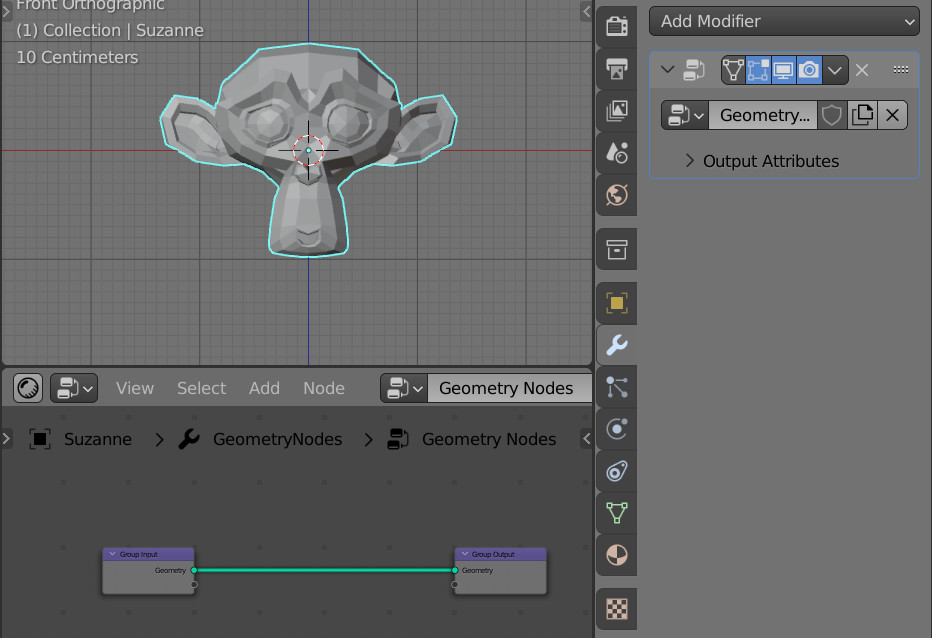
Add “Suzanne” to the scene (shift+a – Mesh – Monkey). Add the “Geometry Nodes” modifier to it and click on the “New” button to create a new node tree.
We will create the flow effect by changing the coordinates of the mesh vertices in such a way that when moving along one axis, for example, the X axis, the coordinates of the mesh vertices along the other two axes will be proportionally change.
First, let’s make a parameter for moving of mesh vertices along the X axis.
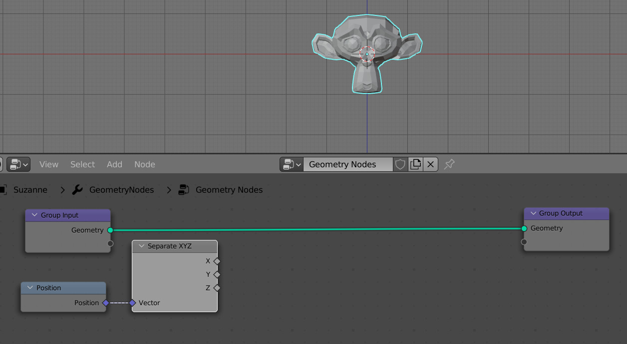
We can get the coordinates of the mesh vertices from the Position node. Add it to the node tree (shift+a – Input – Position).
Add a Separate XYZ node to the scene (shift+a – Vector – Separate XYZ) and feed in the positions of the mesh vertices from the Position node to it. Now we will get separate coordinates along the three axes X, Y and Z, for each vertex of the mesh.
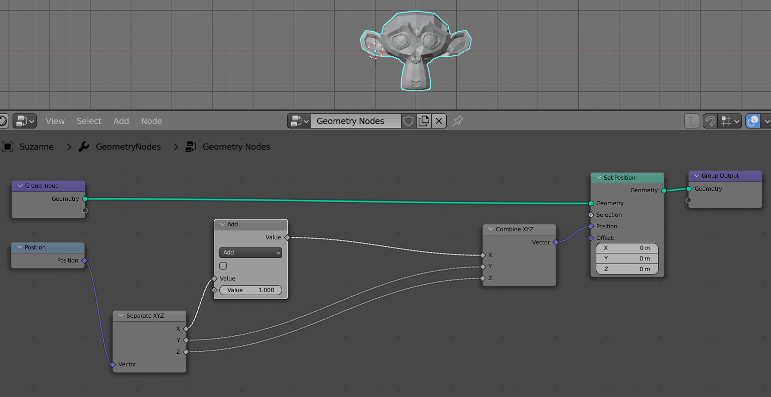
Add an Add node (shift+a – Utilities – Math) with which we will control the movement of mesh vertices along the X axis, adding the value of this node to their X coordinate. Link the X coordinate from the Separate XYZ node to it.
Let’s add a Combine XYZ node to combine the separated X, Y and Z coordinates back. Connect the Y and Z inputs and outputs of the Separate XYZ – Combine XYZ nodes directly, as long as we do not change these coordinate components. And to the X input of the Combine XYZ node, we will link the summ value of the vertex coordinate and a value from the Add node.
To assign new coordinates to the mesh vertices (the original coordinate plus the value from the Add node), append the Set Position node (shift+a – Geometry + Set Position) to the main geometry node tree branch and link the coordinates from the Combine XYZ node with the Position input of this node.
Now we can move the mesh along the X axis simply by changing (scrolling with the mouse) the value in the field of the Add node.
We can modify the Y and Z mesh vertices coordinates according to the X coordinates simply by their multiplication. To do this, add two Multiply nodes to the tree (shift + a – Utilities – Math, switch to Multiply mode) and embed them in the branches for the Y and Z coordinates. Feed the value from the X coordinate to their free inputs.
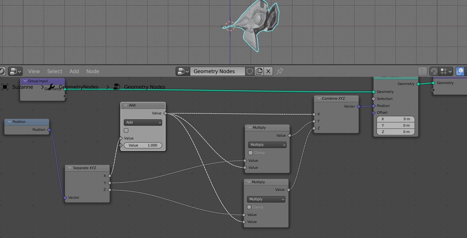
Just now we can see some mesh distortion.
To make the mesh properly mirrored along the X axis, add another Math node to the tree (shift+a – Utilities – Math), switching it to Absolute mode. Insert it before the multiplication nodes.
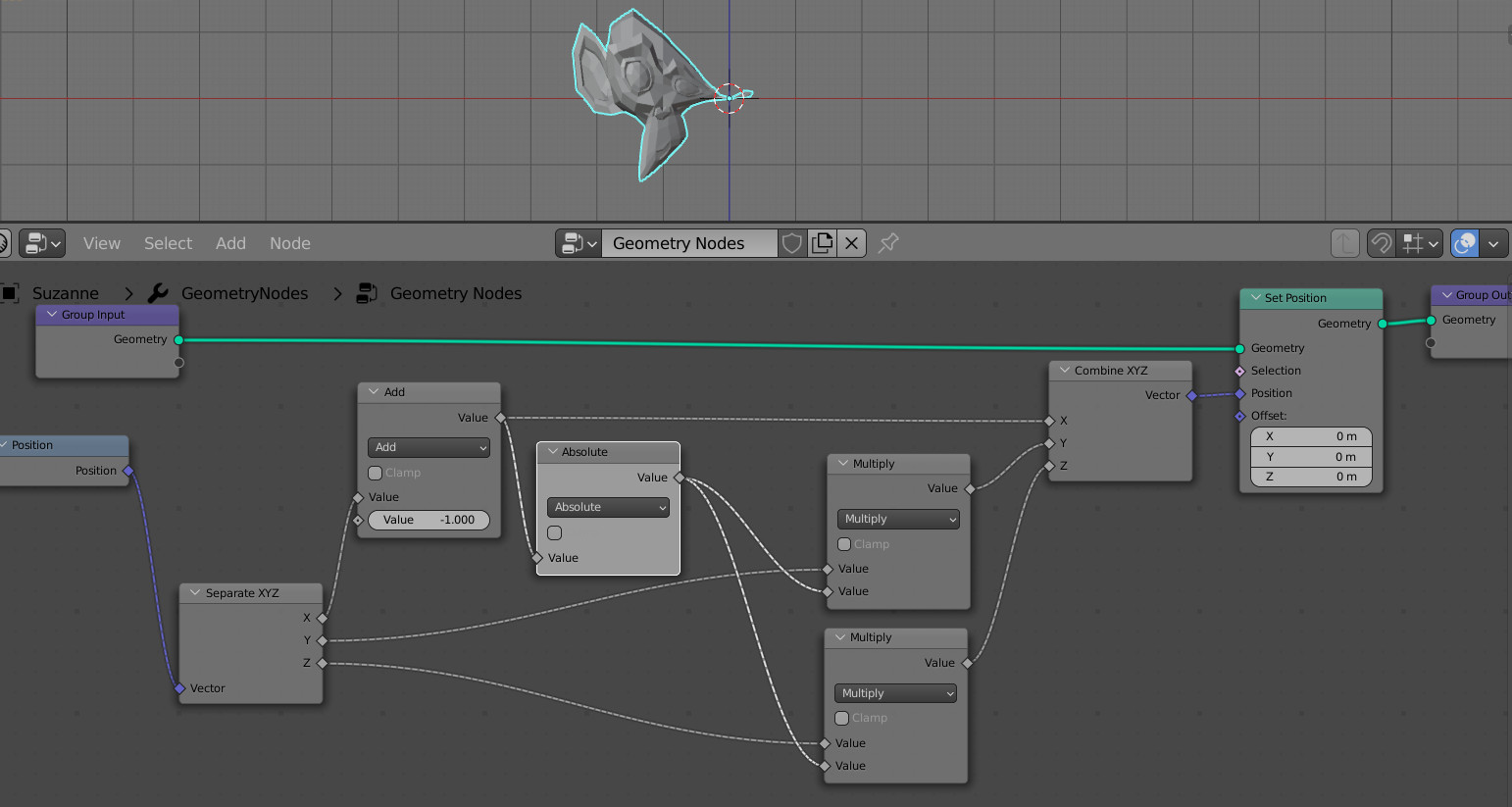
This node helps to get the absolute values of the X axis vertiex coordinates makes it always positive. Now the mesh is properly mirrored around its origin point.
The mesh distortion effect works along the entire X axis. Let’s limit it to a range from -1 to 1.
Add another Math node to the node tree, switching it to the Minimum mode. Insert it next to the Absolute node.
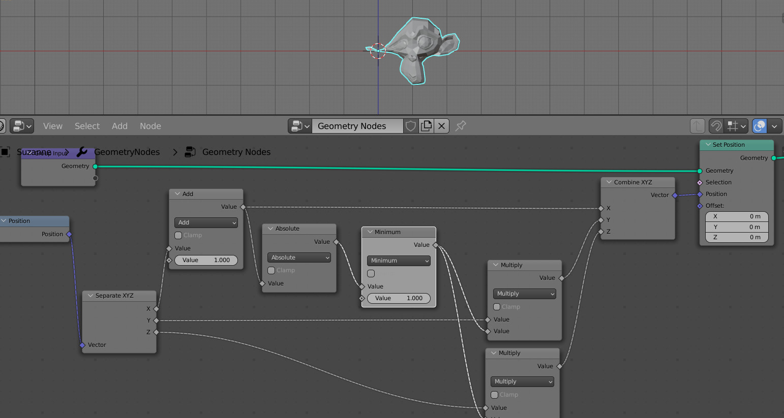
This node compares the X-coordinate with the number in the second input (1.0 in our case), and if it is less – returns the coordinate, else it returns this number (1.0).
We multiply the Y and Z coordinates by the value from this node, so in the range from -1 to 1 (negative values are converted to positive by the Absolute node), we multiply the Y and Z coordinates by the X coordinate, and outside this interval – multiply by 1, and nothing changes outside the given interval.
Now, by sliding the value in the Add node, we see how Suzanne flows from one position to another around its origin point.
To make the effect smoother, let’s add a Subdivision Surface modifier to the mesh.