Let’s look at how we can use displacement with the “Geometry Nodes” in Blender.
 Content on Patreon
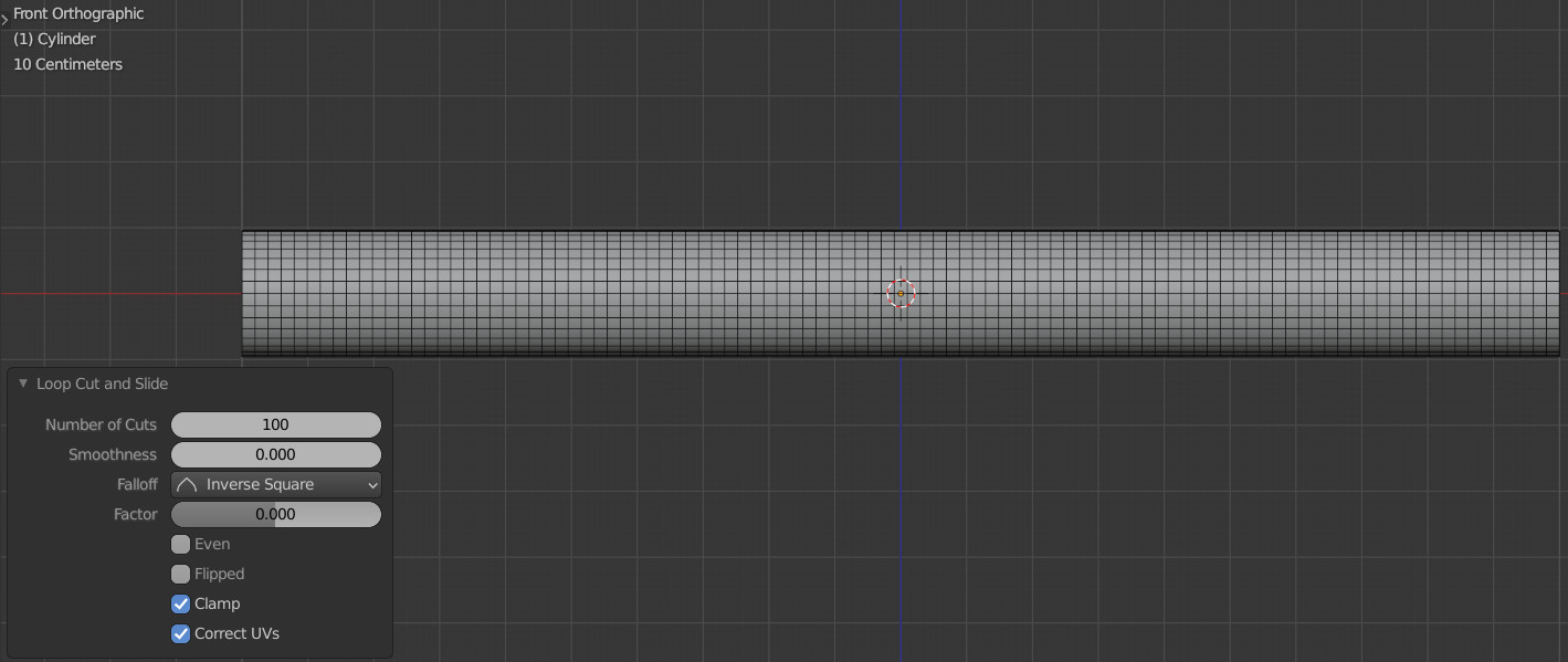
First, add a cylinder (with the 0.1 diameters, without upper and lower closing polygons) to the scene: shift+a – Mesh – Cylinder.
Switch to edit mode (tab) and add edges to make the uniform grid: ctrl+r – 100 – Enter.
Displacement needs the mesh to be as dense as possible.
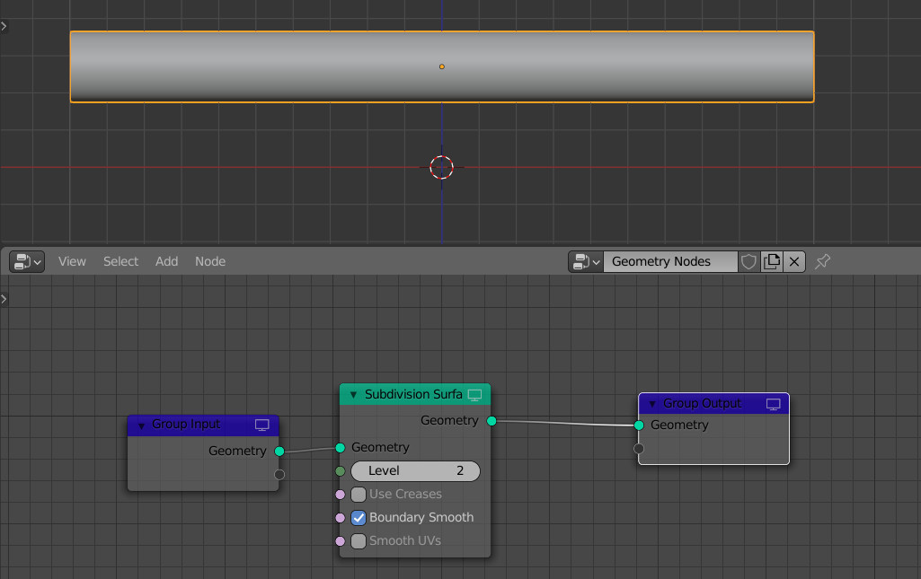
To enable geometry nodes for the current mesh, add the “Geometry Nodes” modifier to it. Next, open the Geometry Nodes editor in a separate window.
Although we have subdivided our cylinder, this is still not enough for displacement. Therefore, add a “Subdivision Surface” node to the node tree for even more subdivision of the mesh: mesh: shift+a – Mesh – Subdivision Surface, and set the subdivision level to 2.
To make displacement, we need to understand that displacement is actually just a shift of vertices by a certain amount along the normal direction.
For any mesh vertex, we always have two vectors: the vector of the position of this point (position) and the vector of the normal for this point (normal). In geometry nodes, these vectors are available through the mesh attributes.
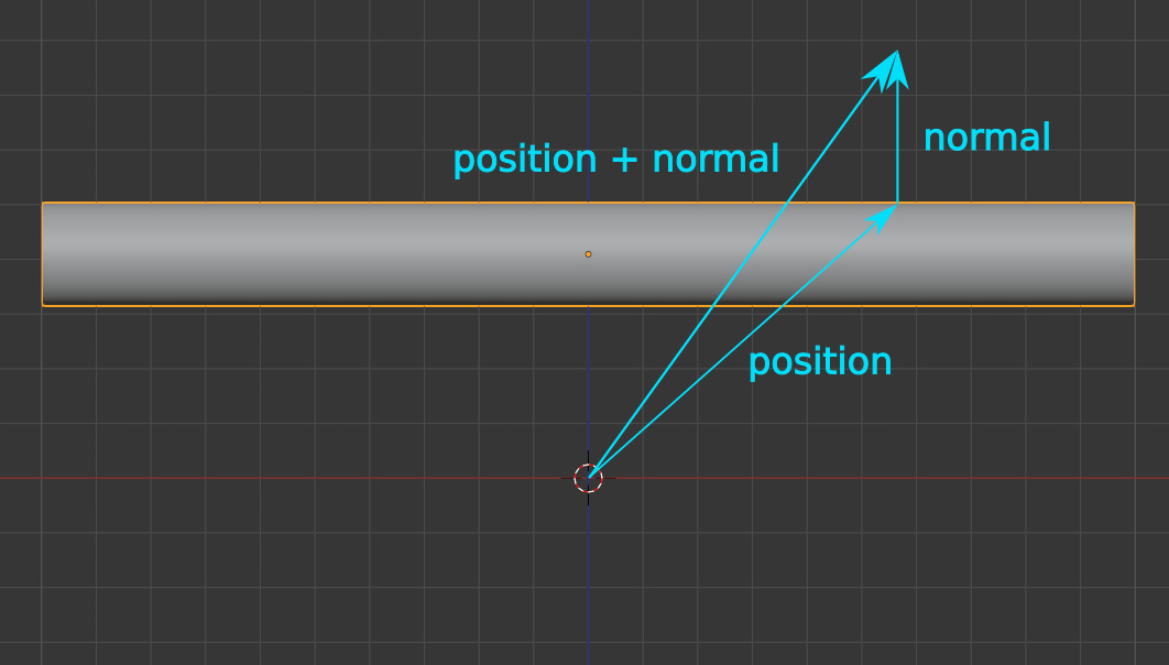
The sum of these vectors will give us the new coordinates of the vertex – where it should be displaced.
We can add these two vectors with the “Attribute Vector Math” node.
Add this node to the node tree: shift+a – Attribute – Attribute Vector Math. In the “A” attribute set “position” (Point – position), in the “B” attribute set “normal” (Face – normal). In the “Result” field, set “position” again. This means that the result of summing the position and normal vectors will overwrite the position vector.

As a result, the cylinder has increased in diameter. This happened because all points on the surface of the cylinder were displaced along the normal by the same amount. Actually, we got a uniform displacement over the entire surface of the mesh.
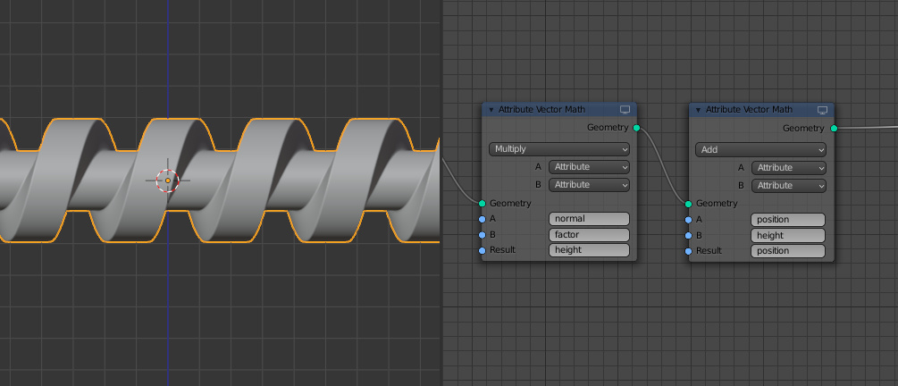
To control the displacement height – how much the vertices will be displaced, the easiest way is to change the value of the normal vector. Let’s multiply the normal vector by a numerical value. This can be done using the same Attribute Vector Math node. Let’s add it between the Subdivision node and the existing one of the same type.
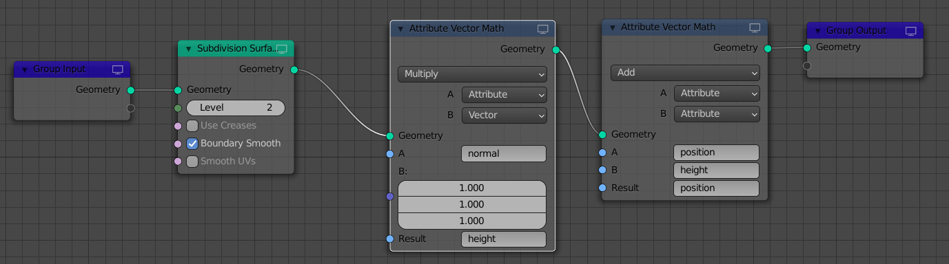
Set “normal” to the “A” field, set the vector type for the “B” field, and set the action to “Multiply”. As a result, we get a normal vector, each of the axial components of which is multiplied by the number that it takes from the vector at the “B” field.
The “normal” vector is always normalized (its length is always equal to one), so we cannot write the result of the multiplication back to the “normal” attribute – it will be normalized again and we will not see any effect. Therefore, type “height” in the “Result” field – to create a new attribute in which the result of the multiplication will be stored.
In the next “Attribute Vector Math” node at the “B” field specify the created “height” attribute, instead of “normal”.
As a result, we get the displacement of the mesh vertices along the normals by the value of the normal multiplied by a factor. Scrolling values in the vector input, we can see how the cylinder’s dimensions change.
However, the displacement on the mesh is still uniform – all points are displaced at the same value. We can use a texture map to set which mesh points need to be displaced.
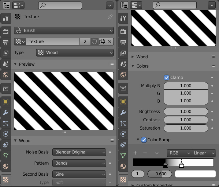
Switch to the object’s textures tab in the Properties window and create a new texture. Set the “Wood” type and enable the “Color Ramp” parameter to give the lines some definition.
To access the texture from the Geometry Nodes editor, the “Attribute Sample Texture” node is used.
Let’s add such a node to our node tree and specify the texture we created in it. For the “Mapping” entry, set the “UV Map” attribute (Face Corner – UV Map). In the “Result” field, specify the name for the new attribute that will control the distribution of the displacement – “factor”.
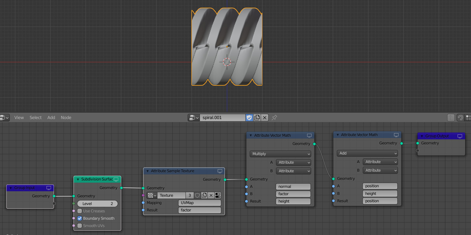
In the next Attribute Vector Math node, change the “B” input from a vector to the “factor” attribute received from the texture node.
As a result, we immediately see how the shape of the cylinder has changed. Displacement works only on areas of the surface along white lines, and there is no displacement on black lines.
This occurs because now we are multiplying the value of the normal not by a constant value, but by the value from the texture: black areas – 0, white – 1.
But now we have lost the ability to manually adjust the displacement height, it is determined only by the texture. Let’s dd an “Attribute Math” node between the “Attribute Sample Texture” and “Attribute Vector Math” nodes to solve this.
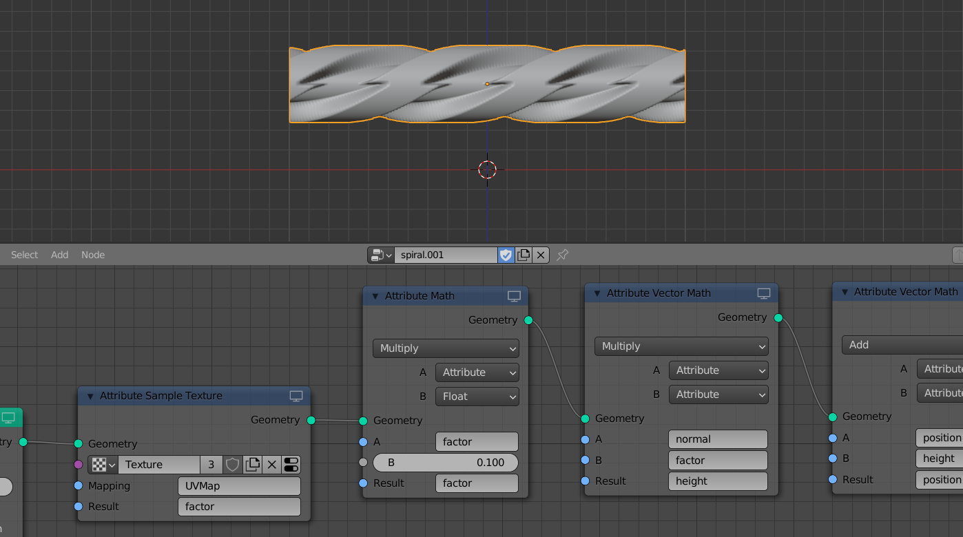
Set the attribute “factor” to the “A” field, at the input “B” we will set a number – to adjust the height of the displacement. Set “Multiply” to the operation, and set the attribute “factor” again to the “Result” field.
Thus, we simply multiply the value obtained from the texture color by a number. This gives us the ability to influence the amount of displacement. By scrolling the value in this field, we can see how the displacement value on the cylinder changes.
To make the result more beautiful, adjust the position of the texture on the cylinder. Let’s add one more “Attribute Vector Math” node to the node tree between the texture node and the subdivision node. Set the “UV Map” attribute to the “A” field, switch the “B” field to vector type, and set the “Multiply” operation. To the “Result” field set the new attribute “mapping” into which the adjusted UV-map will be translated.
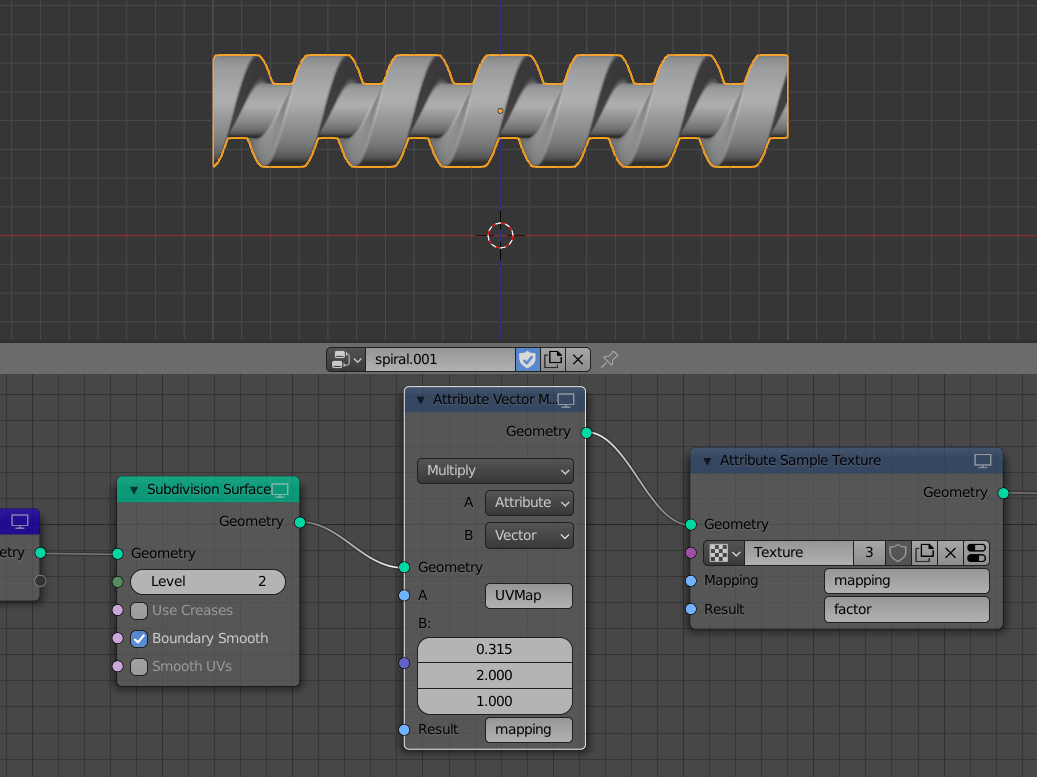
For the “Mapping” field of the texture node, change the attribute to the “mapping”. It remains only to set the position of the texture by adjusting the values in the vector field to get a good result.
Full node tree:
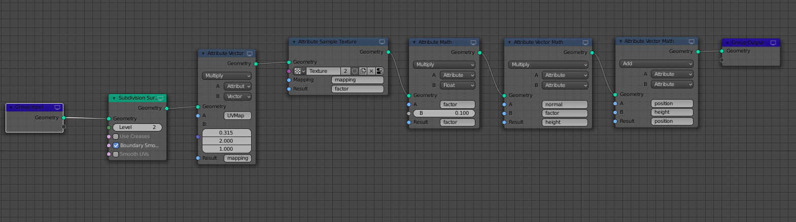
Some of the nodes don’t exist in the newest version. Thus, I’ve made substitutions to allow for the newest version. See the blend file I made.
Great!