With Geometry Nodes in Blender, we can control the geometry of the mesh, focusing on its bending – the angle between adjacent polygons. This allows, for example, to separate the smooth “organic” geometry and sharp “hard surface” geometry.
 .blend file on Patreon
The main tool that allows us to differentiate between smooth and sharp geometry is the Edge Angle node, which determines the angle between two adjacent polygons.
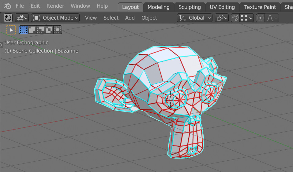
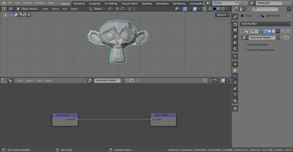
Add Suzanne to the scene (shift + a – Mesh – Monkey), assign her the Geometry Nodes modifier, and click on the New button to create the initial node tree.
As an example, let’s make a visualization of the comparison between the angle of two polygons and a numerical value.
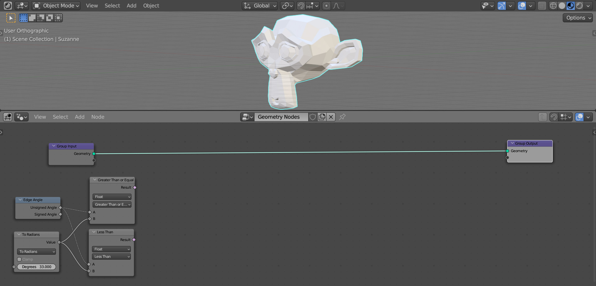
Add an Edge Angle node (Mesh – Read – Edge Angle).
Add two Compare nodes to compare the angle with a number (shift + a – Utilities – Compare). Switch the first node to the “Grater Than or Equal” mode – this condition will correspond to the angle between the polygons being greater than or equal to the specified one. Switch the second one to the “Less Than” mode – the angle between the polygons is less than the specified one. Link the “Unsigned Angle” output of the Edge Angle node with the “A” inputs of both Compare nodes.
The Edge Angle node produces result in radians. To compare with the degrees, add a Math node (shift + a – Utilities – Math – Math) and switch it to the “To Radians” mode. Link its “Value” output with the “B” inputs of both Compare nodes.
We defined two branches, one for angles greater than a given one and the second for angles less than a given one.
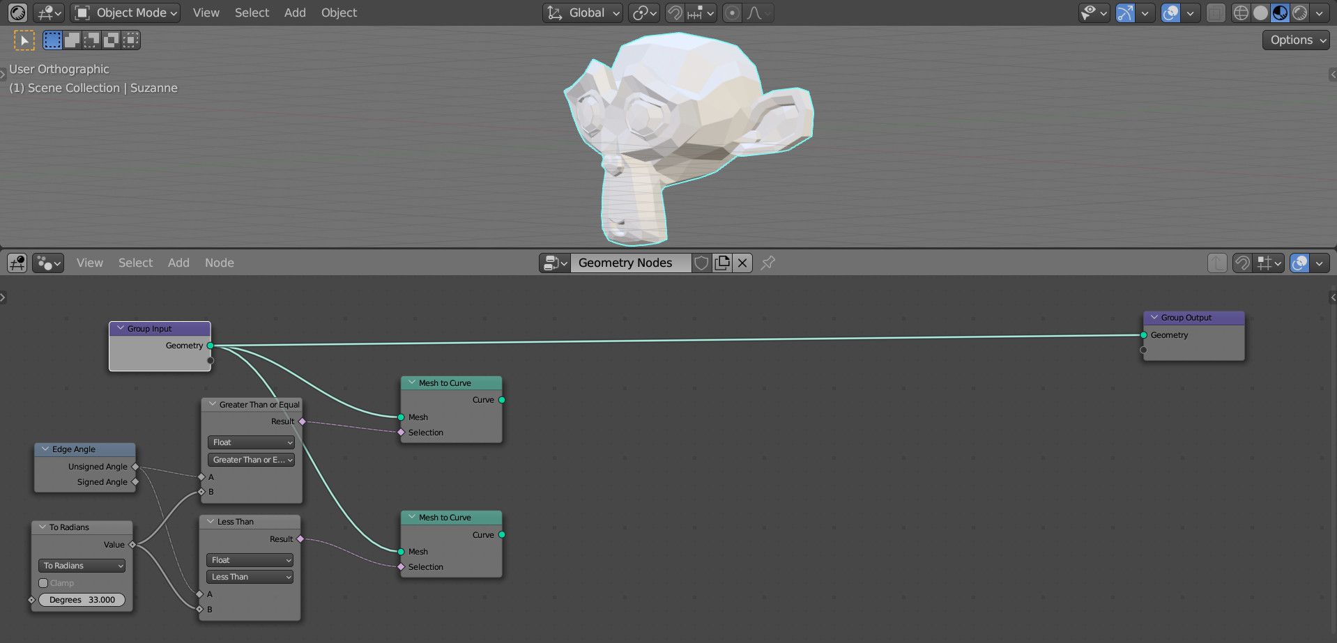
Add two Mesh to Curve nodes (shift + a – Mesh – Operators – Mesh to Curve) and connect them to the main geometry branch of the node tree. The outputs of the Compare nodes link with the corresponding “Selection” inputs of these nodes.
Add a Curve to Mesh node to each branch (shift + a – Curve – Operators – Curve to Mesh). And also add a Curve Circle node (shift + a – Curve – Primitives – Curve Circle). Link its “Curve” output with the “Profile Curve” inputs of both Curve to Mesh nodes. For the “Radius” field, set the value to 0.01.
This way, we stroke along the edges of the mesh using curves.
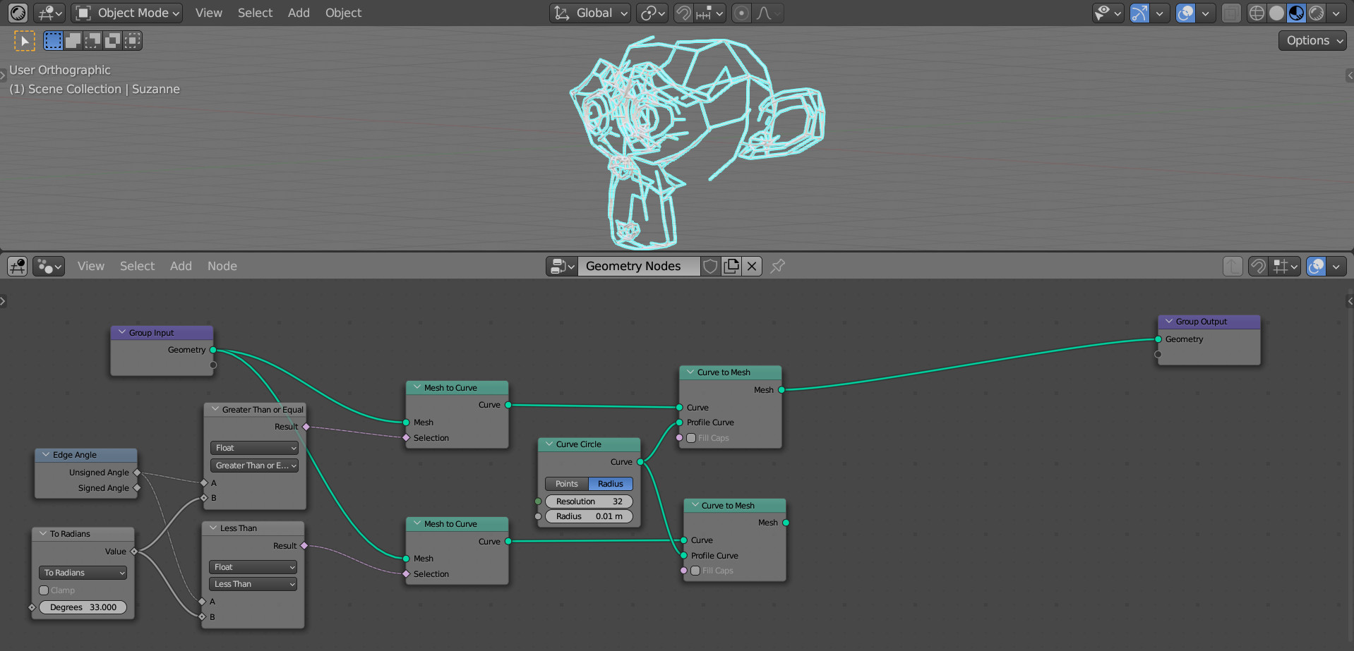
If we now connect one of our branches to the Group Output node, we will see part of the stroke that corresponds to the condition we set for the angle – more or less. By changing the angle in the To Radians node, we can see changes in the stroke.
Add a Set Material node to each branch (shift + a – Material – Set Material). Create two materials with different colors and specify them in the fields of each Set Material node.
Now all we have to do is combine all the geometry using the Join Geometry node (shift + a – Geometry – Join Geometry). Add it to collect all the branches of geometry into one.
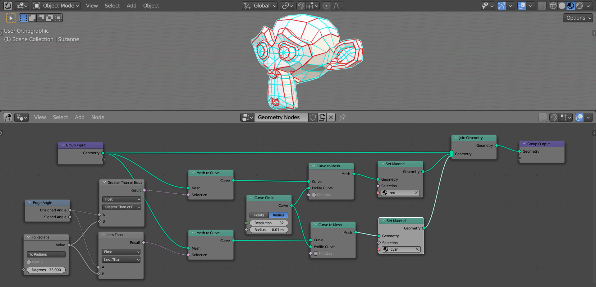
Now we can conveniently track the angle – edges for which the adjacent polygons have an angle greater than or equal to the specified one, will be painted in one color, and those where the angle between the polygons is less than the specified one will be colored in another.
Changing the value of the given angle in the To Radians node, we can visually observe compliance with the condition on the mesh.