All procedural textures in Blender are based on math. Even such irregular structures as “Voronoi” and “Noise” are actually generated according to the mathematical formulas. An exact mathematical algorithm is sewed up into each base material node to obtain the desired image as a result.
We can not specify such algorithms in Blender in the usual mathematical format. However, among other nodes, Blender provides us the “Math” nodes – the wrap over simple mathematical operations. Using these nodes we can build complex mathematical algorithms yourself, generating interesting textures.
As an example let’s create a procedural texture with a simple circle image.
Prepare the scene:
Add a plane
shift+a – Mesh – Plane
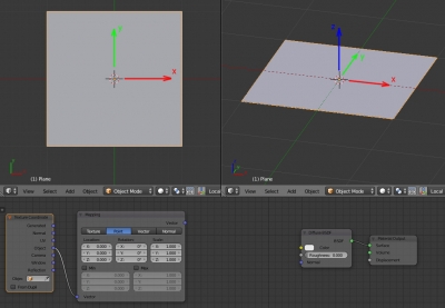
Here we will draw our texture. Assign the default material to it. Add two nodes: “Texture Coordinate” and “Mapping” in addition to the existing nodes in the Node Editor window:
shift+a – Input – Texture Coordinate
shift+a – Vector – Mapping
Connect the “Object” output of the “Texture Coordinate” node to the “Vector” input of the “Mapping” node. This way we assign the Object coordinate system to the plane surface. It means that the center of the texture coordinates coincides with the plane origin (with the mesh origin – small yellow dot), and the texture coordinate axes are directed the same way as the plane coordinate axes.
Now let’s pay attention to the initial data we have. These are the values of the X, Y, and Z coordinates in three-dimensional space, which we get from the “Vector” output of the “Mapping” node.
All procedural textures are three-dimensional and are described not in two coordinates, but in three. So we need to create not a circle but a sphere in three-dimensional space. The sphere section along the Z-axis will give us the circle we need. Our plane just does this section.
It’s time to pick up the math handbook and search for a formula that connects the available data (the X, Y, and Z coordinates) to the sphere shape we need. It’s easily found:
Now we need to recreate this formula with Blender nodes.
Add a node to split the “Vector” output into individual X, Y and Z coordinates:
shift+a – Converter – Separate XYZ
and connect it to the “Mapping” node. Now we have access to the coordinates to build the formula.
Now we consistently recreate the formula with the nodes.
Add the “Math” node:
shift+a – Converter – Math
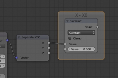
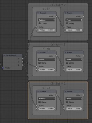
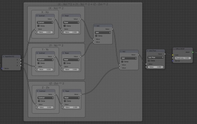
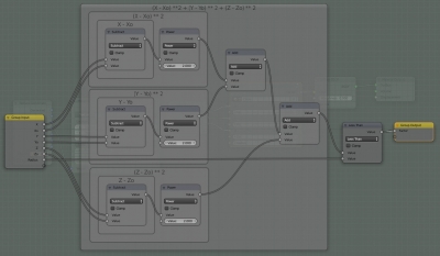
and switch it to the “Subtract” mode. The lower input value subtracts from the upper input value of the node in this mode. Connect the upper input with the X coordinate. Set the lower input value to zero (X0 = 0) – our circle will be drawn from the origin. This defines the “X – X0” part of the formula.
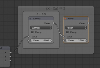
Add the “Math” node again and switch it to the “Power” mode. Connect the upper input with the “Value” output of the “Subtract” node, set the lower input value to 2. It squares the “X-X0” value.
Build the same groups for the Y and Z coordinates.
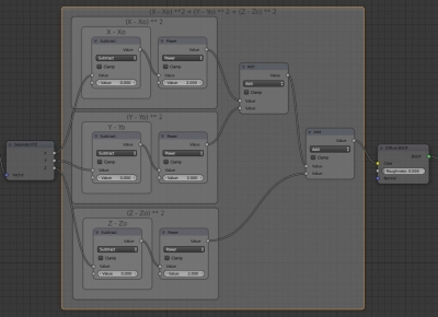
To summarize all three equation parts, add two more “Math” nodes with the “Add” mode. Connect them sequentially for all three formula blocks.
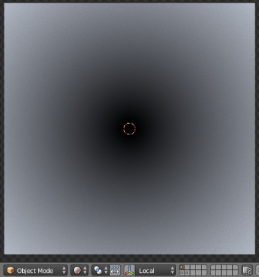
Connect the last “Add” node output to the “Color” input of the “Diffuse” node and in the “3D_View” window switch to the “Rendered” mode to view the result.
We got the desired circle, but it is blurry. Because we did not restrict the right-hand side of the equation – the radius.
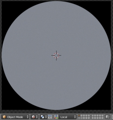
Insert another “Math” node between the “Duffuse” node and the last “Add” node. Switch it to the “Less Than” mode. Connect the upper input with the “Add” node output, and set the second one to 1. Now the calculation result less than 1 will be equal to 1, and all that is greater is equal to 0. Now we get the exact procedural circle with radius 1.
The whole node tree looks like:
We can combine all the math into a node-group
ctrl+g
and use the procedural texture with the circle in our renders.
We can control the circle location and size by modifying the values in the “Mapping” node.
