In order to make control over the direction of mesh vertices normals in Blender more visual, we can create a simple bunch of nodes in Blender Geometry Nodes.
 .blend file on Patreon
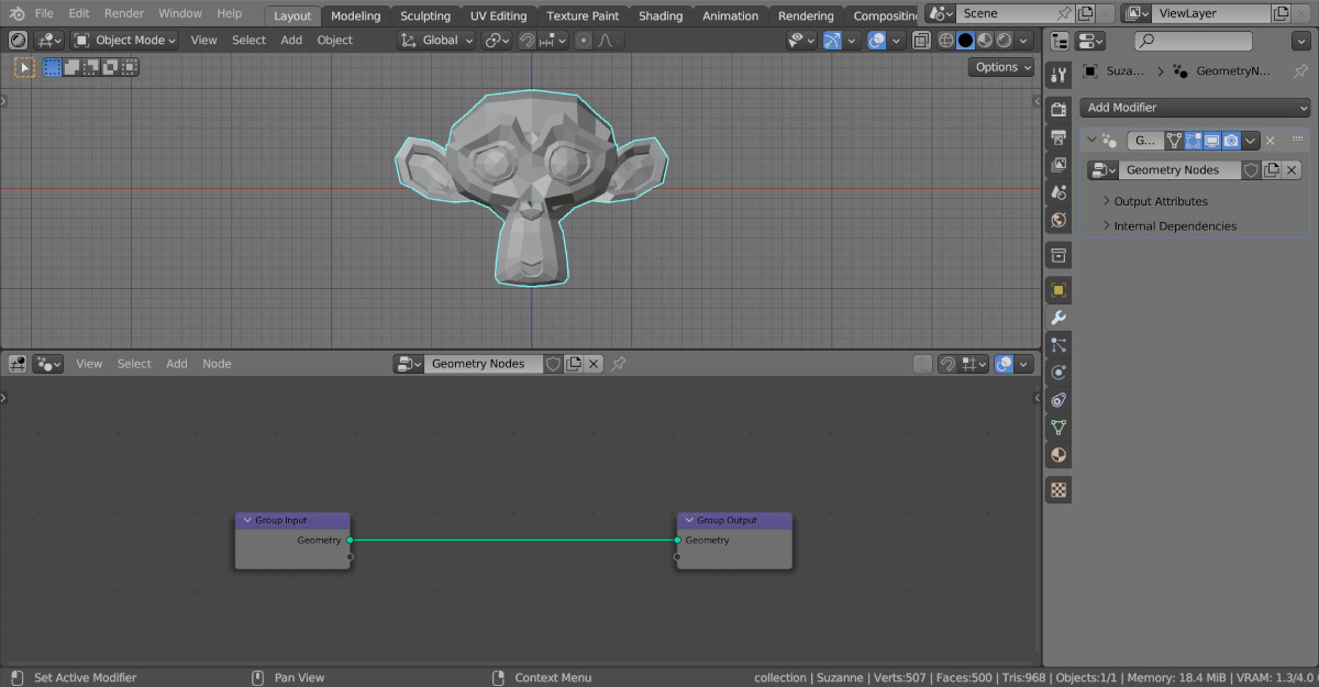
Let’s add Suzanne to the scene (shift + a – Mesh – Monkey), assign the Geometry Nodes modifier to it, and initiate the empty tree of nodes by clicking on the New button.
Normals are easiest to visualize using mesh objects consisting of two points and one edge between them. The Geometry Nodes allow us to create such a mesh using the Mesh Line node.
Add the Mesh Line node (shift + a – Mesh – Primitives – Mesh Line). Set the value of its “Count” field to 2. This node will create the required mesh for us to display the normal.
To distribute our meshes-normals across the vertices of the object, we can use the Instance On Points node, which places an instance of the passed object at each point of the given mesh.
Add the Instance On Points node (shift + a – Instances – Instance On Points) to the main branch of the node tree. The “Mesh” output of the Mesh Line node link with the “Instance” input of the Instance On Points node.
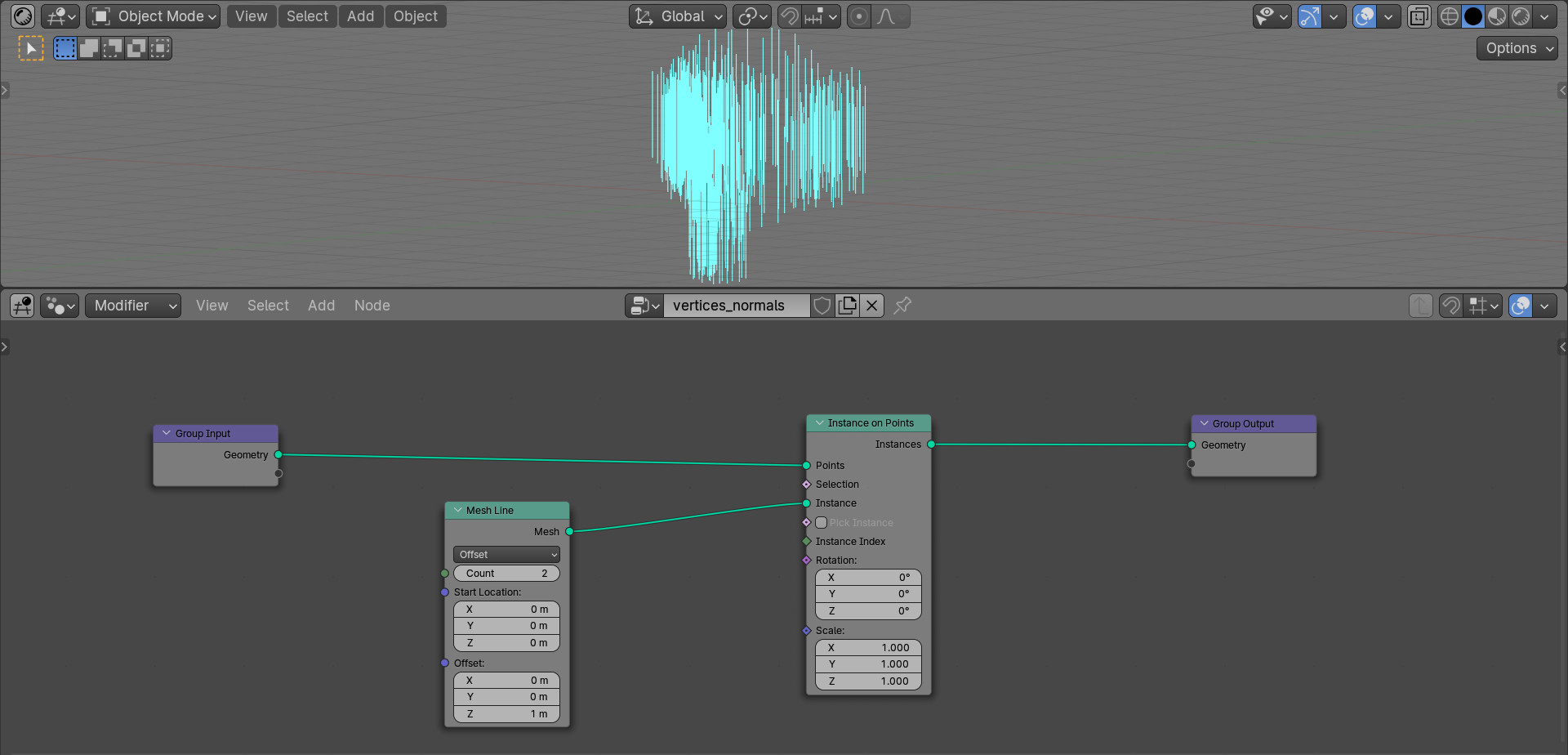
Now on each vertex of the mesh we have a vertical mesh-line.
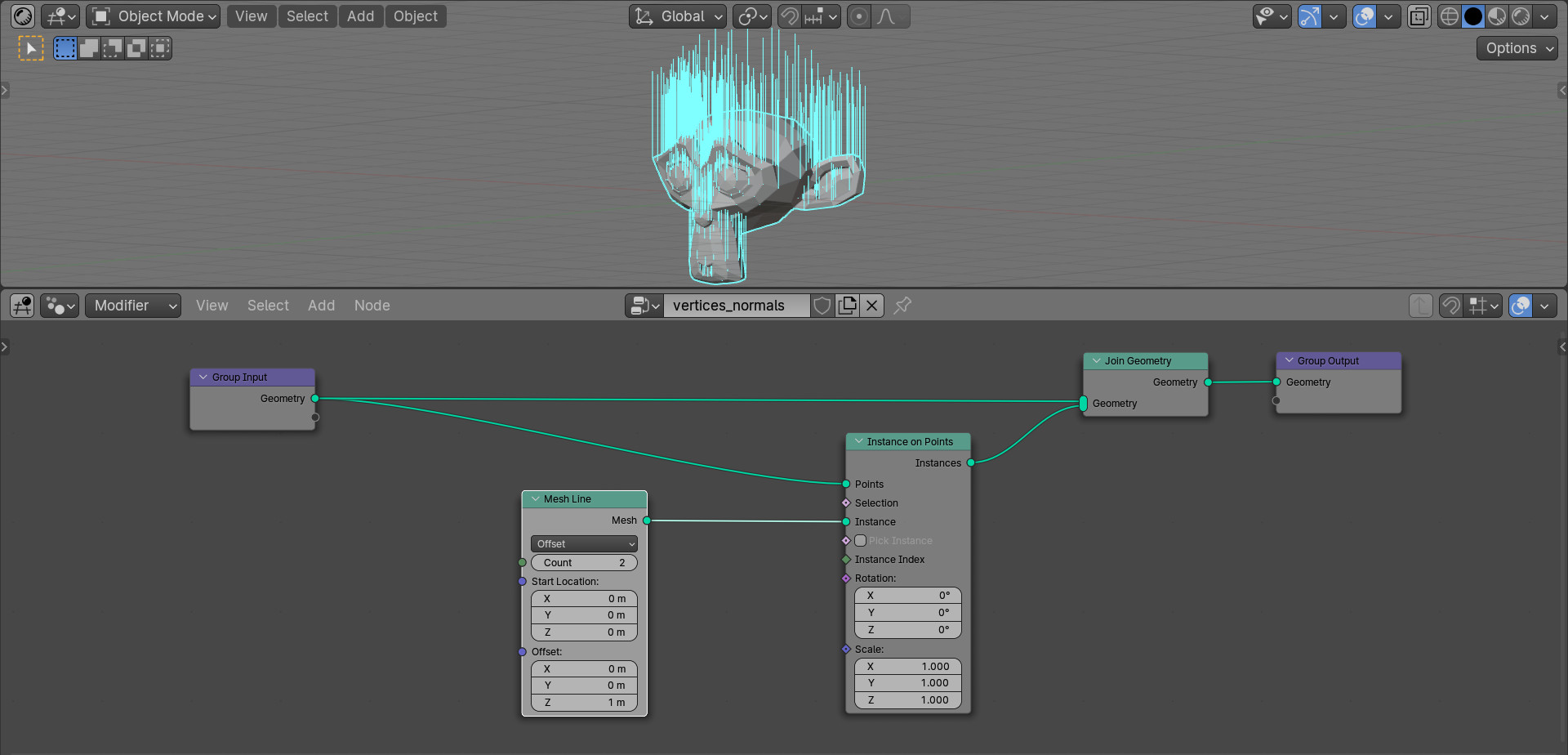
For better viewing, add the Join Geometry node (shift + a – Geometry – Join Geometry) to the end of the node tree and feed it links from the original mesh geometry and the set of lines we created.
Now all the lines we have created are directed upward along the Z axis. To align them in accordance with the direction of the normals of the mesh vertices, we can use the Align Euler to Vector node (shift + a – Utilities – Rotation – Align Euler to Vector). Switch the “Axis to Align to Vector” field to the value “Z”.
Add the Normal node (shift + a – Geometry – Mesh – Normal). From this node we will get the real directions of the vertex normals.
To rotate our mesh-lines along the normals of the mesh vertices, link the normal vector from the Normal with the “Vector” input of the Align Euler to Vector node. And to apply the resulting rotation to our lines, link the “Rotation” output of the Align Euler to Vector node with the “Rotation” input of the Instance on Points node.
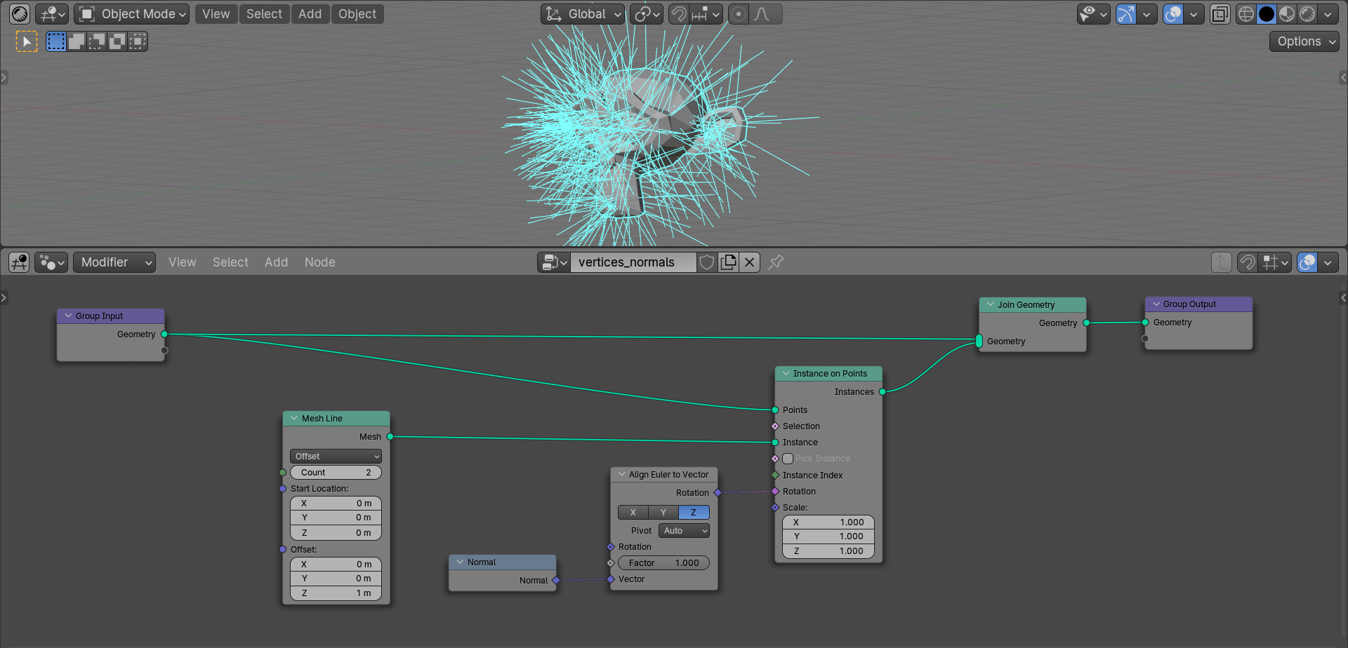
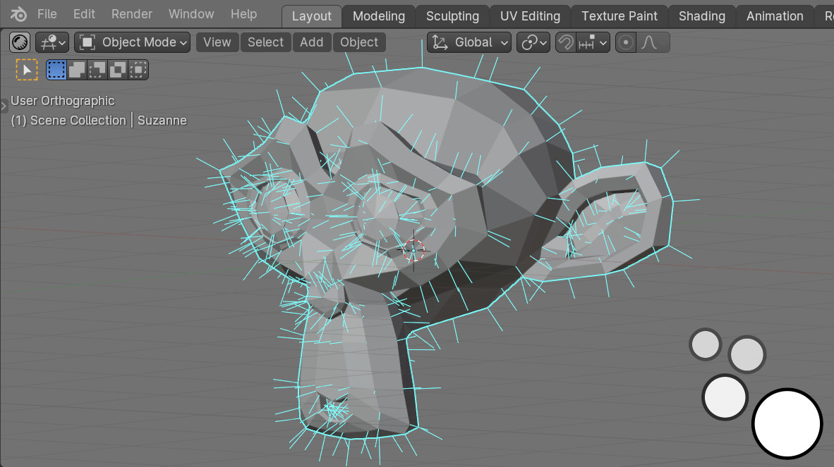
As we can see, the lines we created now reflect the direction of the normals of Suzanne’s vertices.
For convenience, we can adjust their length. Add the Combine XYZ node (shift + a – Utilities – Vector – Combine XYZ) and links its “Vector” output with the “Offset” input of the Mesh Line node. Set the value of the “Z” field of the Combine XYZ node to 0.25.
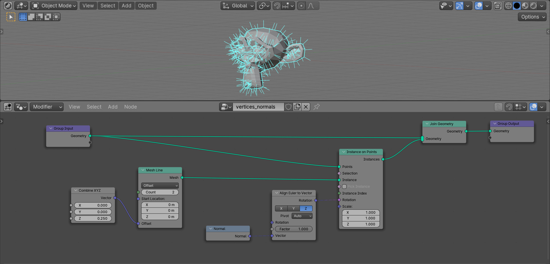
Now we can easily control the length of the displaying normal simply by changing the value of this parameter.
For even greater convenience, we can place it on the modifier panel by simply creating the link from the “Z” input of the Combine XYZ node to the empty output of the Geometry node.
In the N-panel we can rename it in a convenient way, for example – Normal Length.
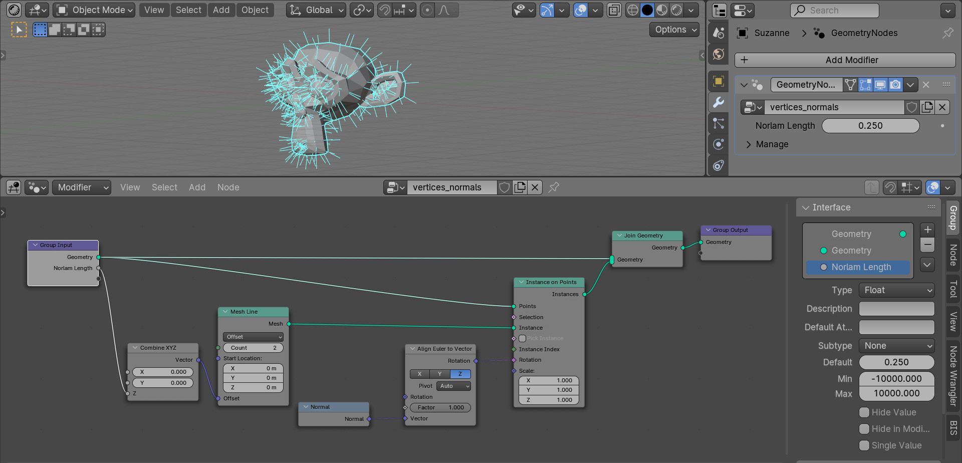
In the modifier panel, this field is now displayed under the specified name. And it’s very convenient to adjust the length of the visualized normals through it.