Bending text along a curve is one of the spectacular techniques for creating various unusual and interesting inscriptions. In Blender, this can be done using Geometry Nodes.

 .blend file on Patreon
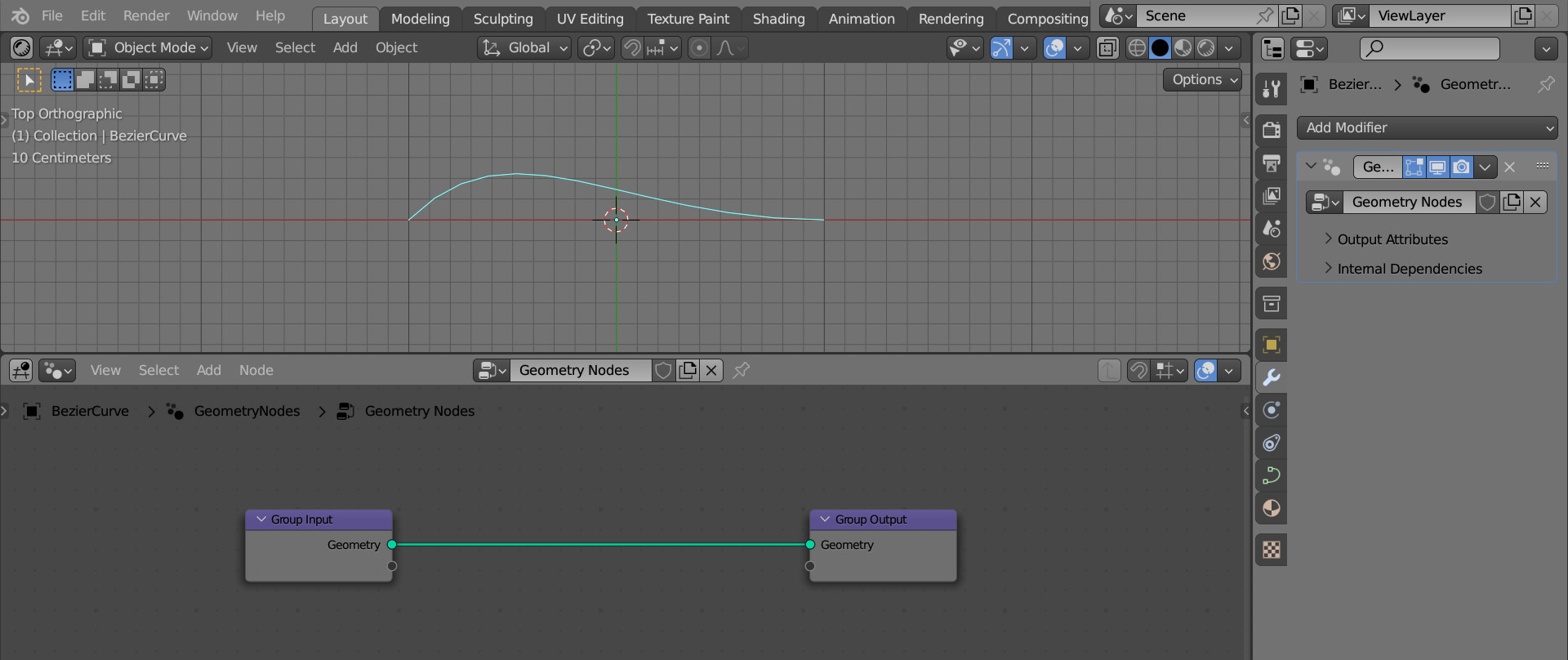
First add a curve to the scene (shift + a – Curve – Bezier), append a Geometry Nodes modifier to it and initialize the starting node tree by clicking on the “New” button.
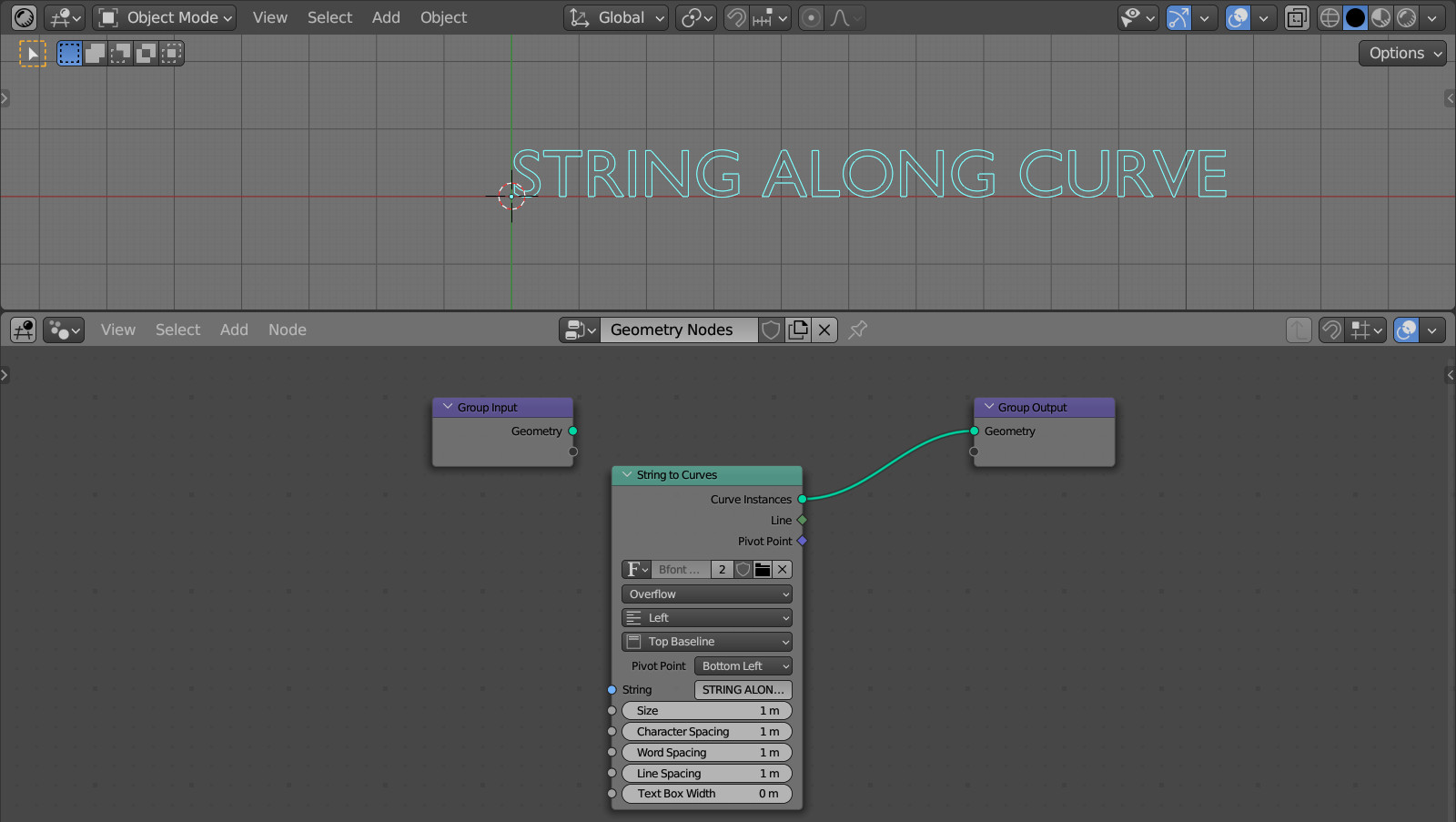
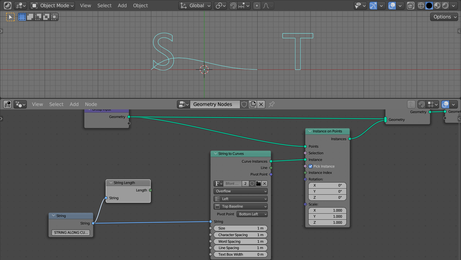
First, add a node that will create a curve geometry from a text string – String to Curves (shift + a – Text – String to Curves). Type any text in the “String” field.
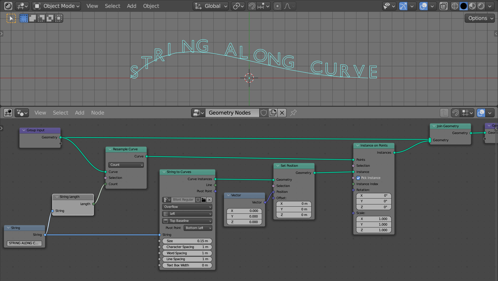
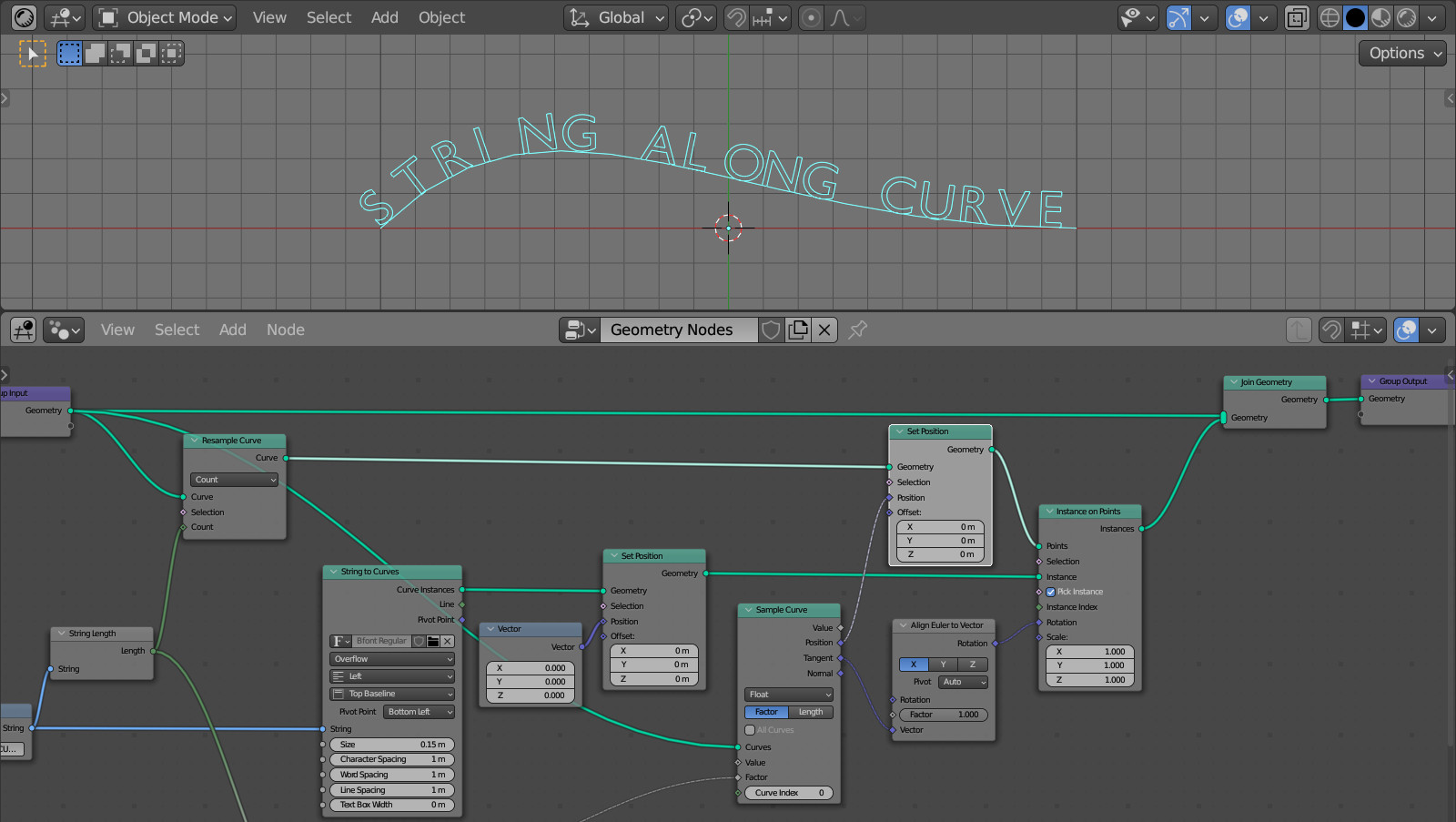
In order for the text to be distributed over the points of the original curve, we can use the Instance on Points node (shift + a – Instances – Instance on Points).
Link the main branch of the tree with its “Points” input to take the points of the curve.
Link the “Curve Instances” output of the String to Curves node with its “Instances” input to place an instance of the generated string at each point of the curve.
Now the entire string is placed at each curve point. On the “Pick Instances” checkbox in the Instance on Points node. Now, at each point of the curve, a single element (single letter) from the set of instances (from the text string), will be placed.
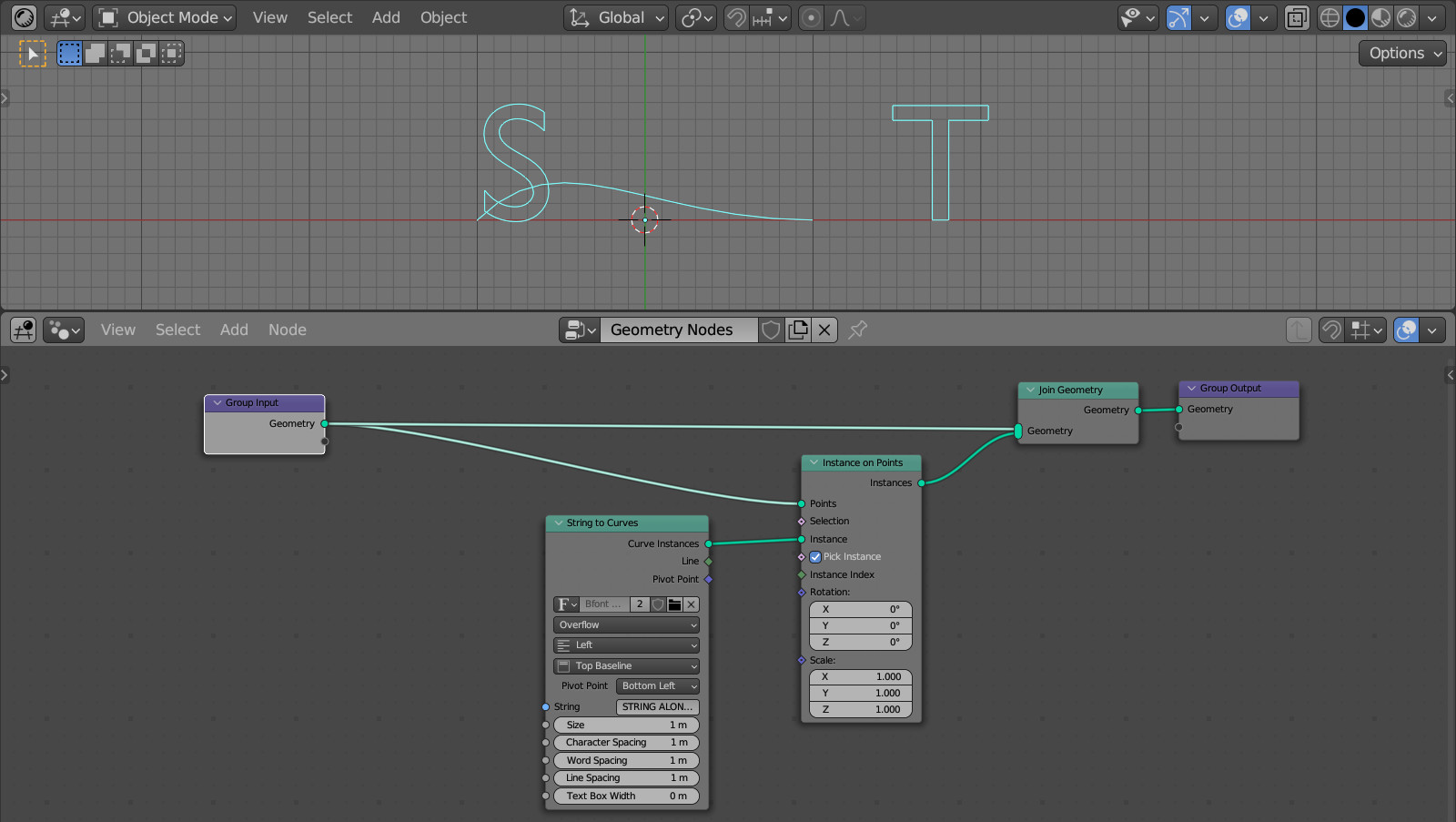
Combine the text string geometry and the curve with the Join Geometry node (shift + a – Geometry – Join Geometry) to see them together simultaneously.
There are only two points on our curve now. So we see only the first two letters from the text string.
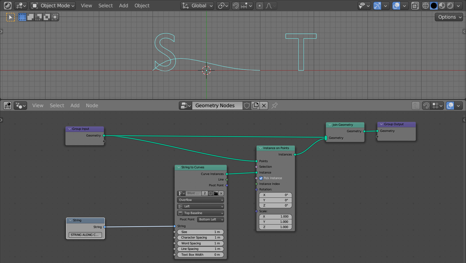
Move the text string to a separate String node (shift + a – Input – String). Copy the source text from the field into it and connect it back to the String to Curves node.
With the String Length node (shift + a – Text – String Length) we can get the number of letters in our text string.
Now, using the Resample Curve node (shift + a – Curve – Resample Curve) let’s subdivide the curve by the number of points equal to the number of letters in our text string.
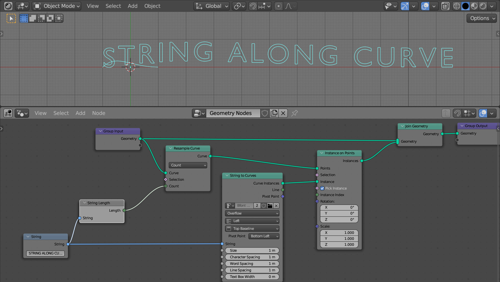
Now we see all the text, but the letters clearly do not match the position of the points on the curve.
This is due to the work of the “Pick Instance” option in the Instance on Points node. For each next point, it selects the next letter from the set of letters, but does not process its offset in the string. Therefore, only the first letter, which has no offset relative to the beginning of the text, is in its own place on the curve.
We can verify this by making the curve more sloping, and then turning the “Pick Instance” checkbox on and off several times.
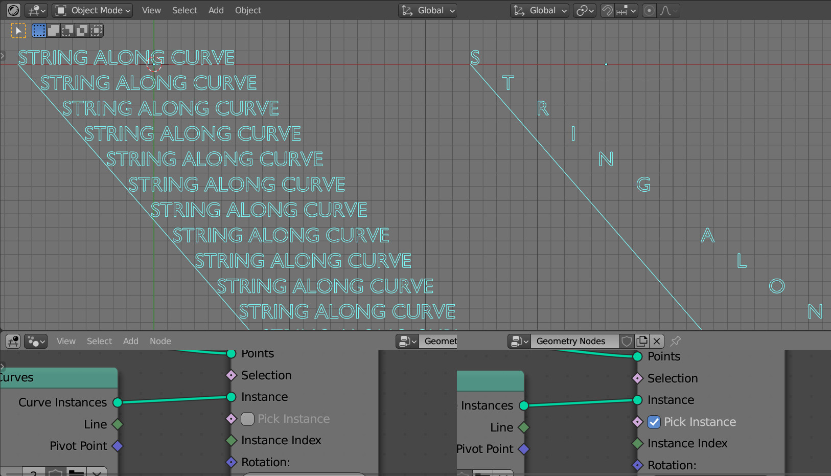
When the checkbox is off, we see the entire string, and when it is on, we see only one letter, but at the place where it is located in the whole string.
To remove offsets, add a Set Position (shift + a – Geometry – Set Position) node right after the String to Curves node. Add a Vector node (shift + a – Input – Vector) and link its output to the “Position” input of the Set Position node. Since all three input fields of the Vector node are equal to 0, we set the location of each letter to the zero point.
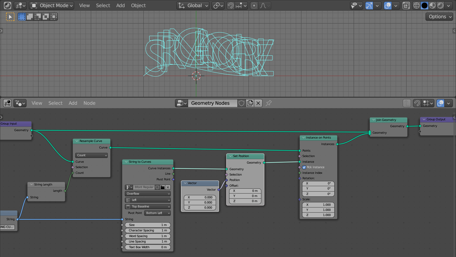
Scale down the letters by changing the “Size” field value of the String to Curves node to 0.15.
To skew the letters to fully fit the curve, we need to rotate the X-axis of each letter so that it lines up with the curve tangent in the point where the letter is placed.
Add an Align Euler to Vector (shift + a – Utilities – Align Euler to Vector) node that will perform the transformation we need. Link its “Rotation” output with the “Rotation” input of the Instance on Points node.
We can get the curve tangent vector from the Curve Tangent node (shift + a – Curve – Curve Tangent). We can add it and link its “Tangent” output with the “Vector” input of the Align Euler to Vector node.
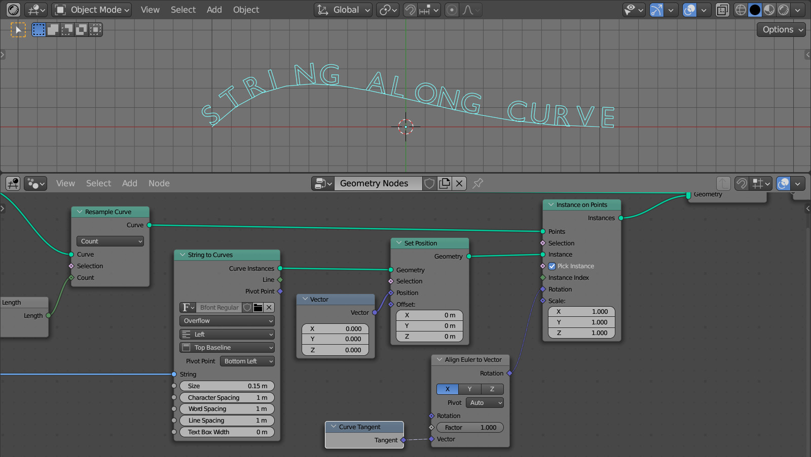
But instead of the Curve Tangent node, it is better to use the Sample Curve node, it also has a “Tangent” output, and it will come in handy later when we will move the text along the curve.
Add a Sample Curve node (shift + a – Curve – Sample Curve) and link its “Curves” input with the “Geometry” output of the Group Input node to get a tangent to the original curve geometry. Link the “Tangent” output in the same way with the “Vector” input of the Align Euler to Vector node.
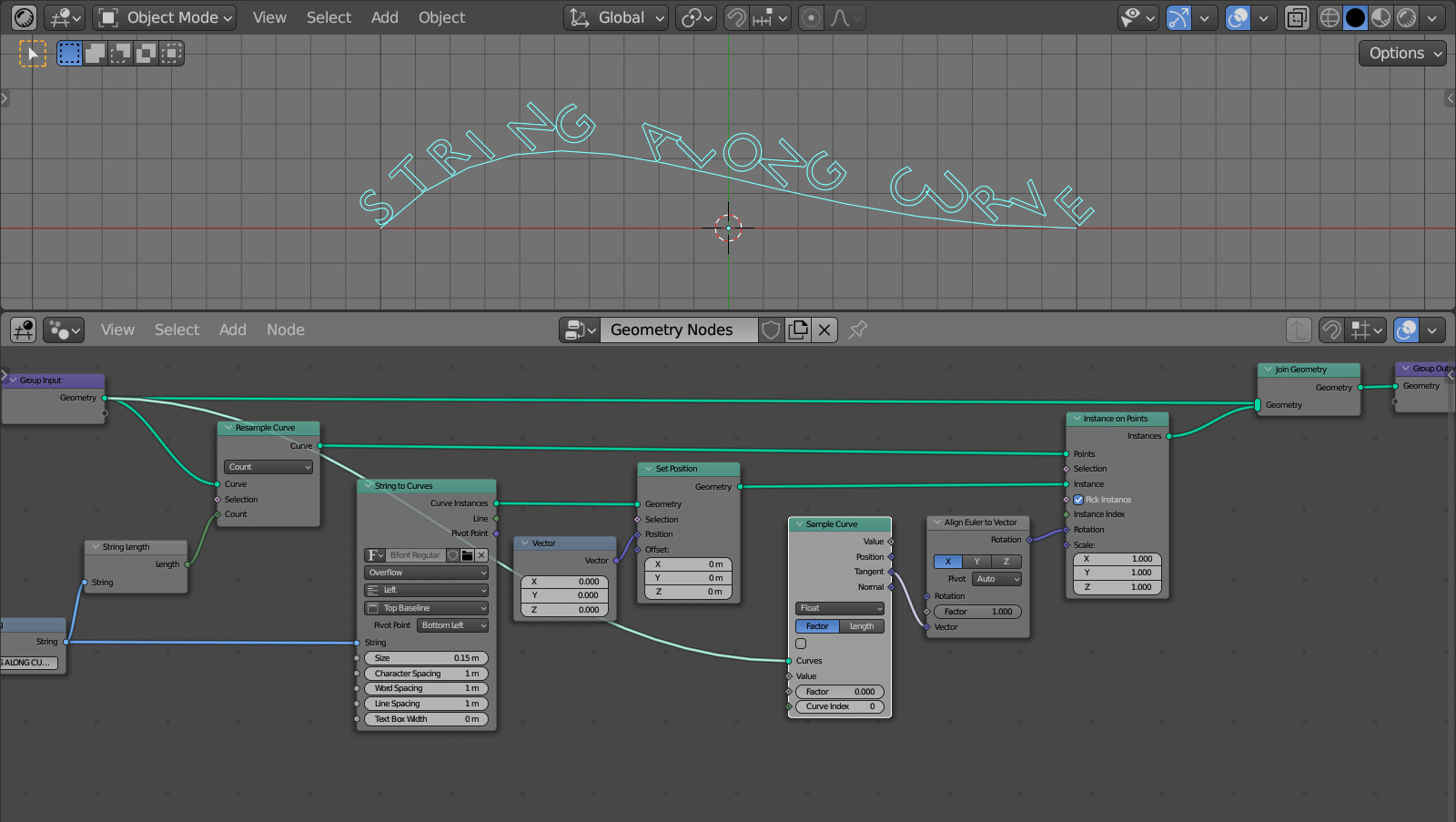
Now all the letters are slanted at the same angle to the curve. The angle was taken from the first letter. To correctly calculate the tangent at each point of the curve, we need to feed the position of these points to the “Factor” input.
Add an Index node (shift + a – Input – Index). We will get a serial number for each point of the curve from it.
By dividing the total number of letters in a string by the ordinal number of each letter, we will get the position for each letter on the curve.
Add a Math node (shift + a – Utilities – Math) and switch it to the “Divide” mode. Link the upper input with the “Index” output of the Index node, and the lower input with the “Length” output of the Curve Length node. Link the output of the Math node with the “Factor” input of the Sample Curve node.
Now each letter is skewed correctly because we calculate the tangent at the points where the letters are located on the curve.
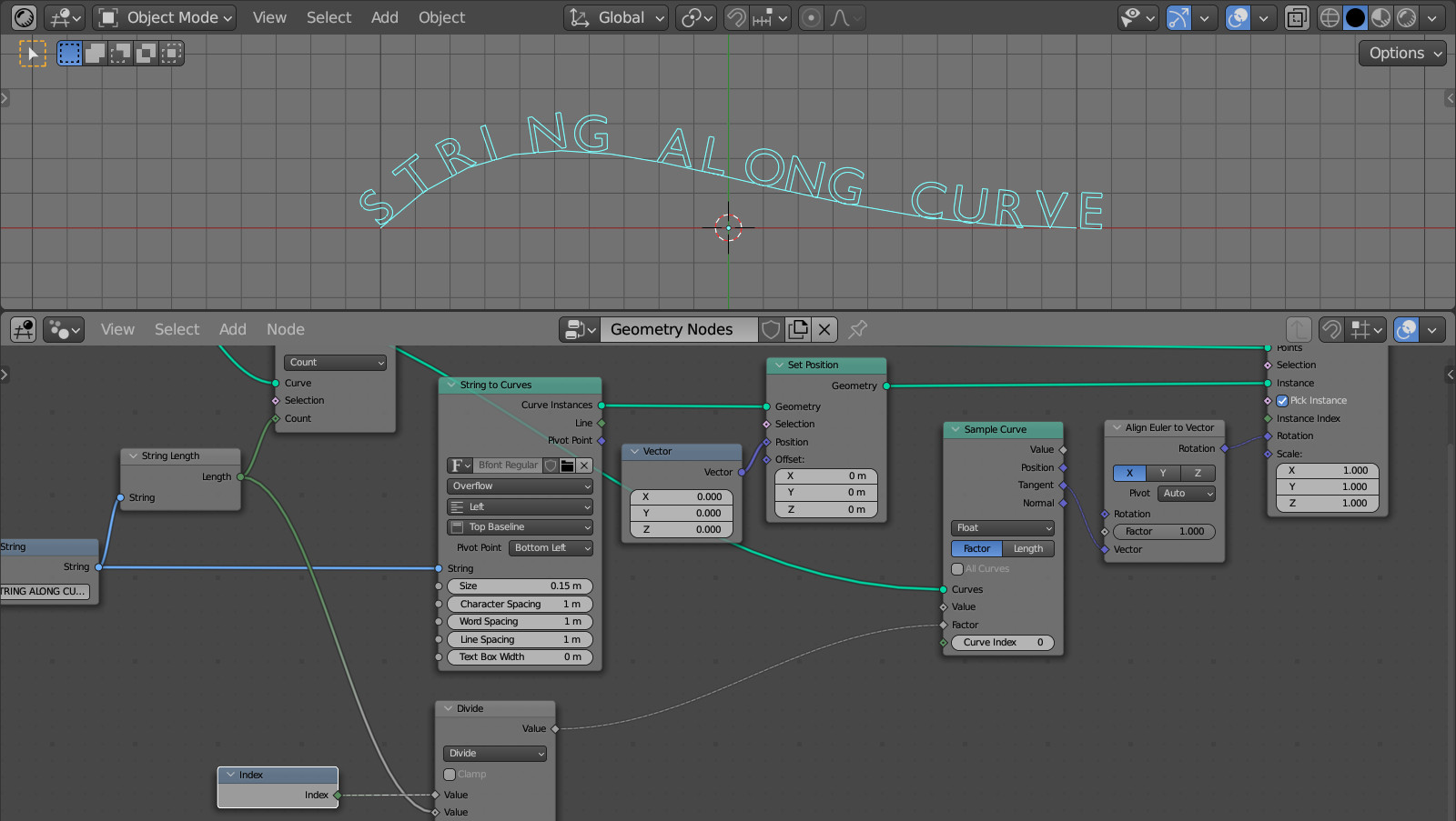
To have an ability to move the letters along the curve, we need to move not the letters themselves, but the points on the curve where they are placed. Add another Set Position (shift + a – Geometry – Set Position) node and put it in a branch between the Resample Curve and Instance on Points nodes so that it affects the curve points.
Link the “Position” output of the Sample Curve node with the “Position” input of the new Set Position node.
Now the position of each point on the curve is determined by the Sample Curve node and controlled through its “Factor” input field.
At present, we put here the result of dividing the number of letters by the ordinal number of the letter, which gives us the position of the points on the curve.
Add a Math node (shift + a – Utilities – Math) in “Add” mode and paste it right after the Divide node.
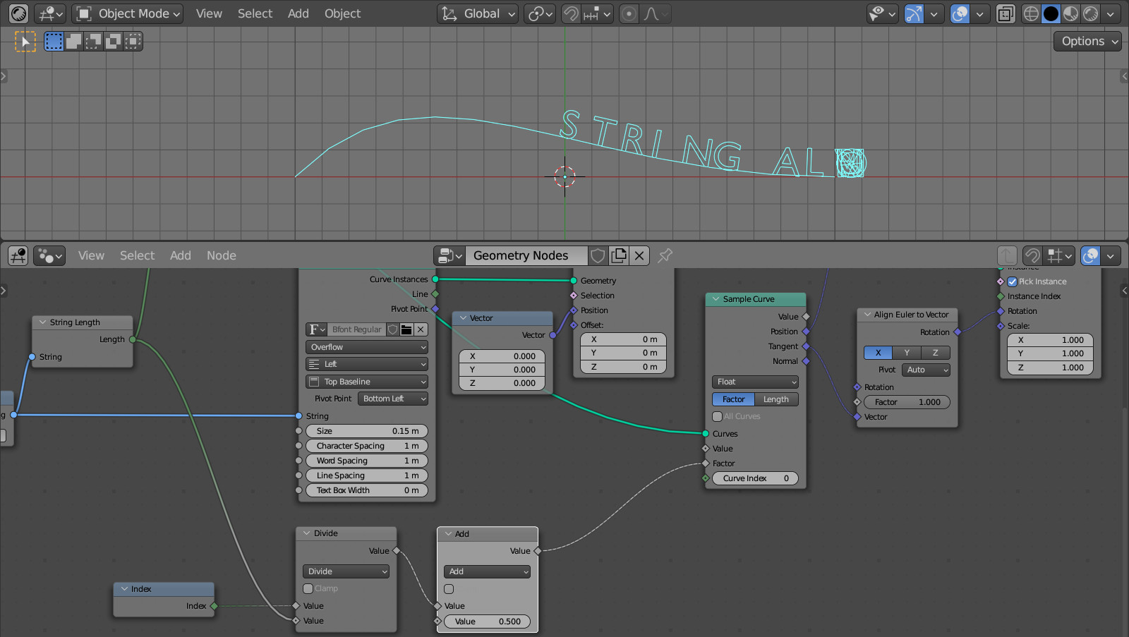
By scrolling the value in the remaining free “Value” input of the node, we can move the letters along the curve.
To keep the letters from bunching up at the end of the curve, add another Math node (shift + a – Utilities – Math) right after the Add node. Switch it to the “Modulo” mode. In the remaining free input, specify the value 1 (because the range of the “Factor” field of the Sample Curve node changes from 0 to 1).
We looped the text string so that the first letter immediately follows the last letter. To leave a gap between the last letter and the first, add a couple of spaces to the end of the string in the String node.
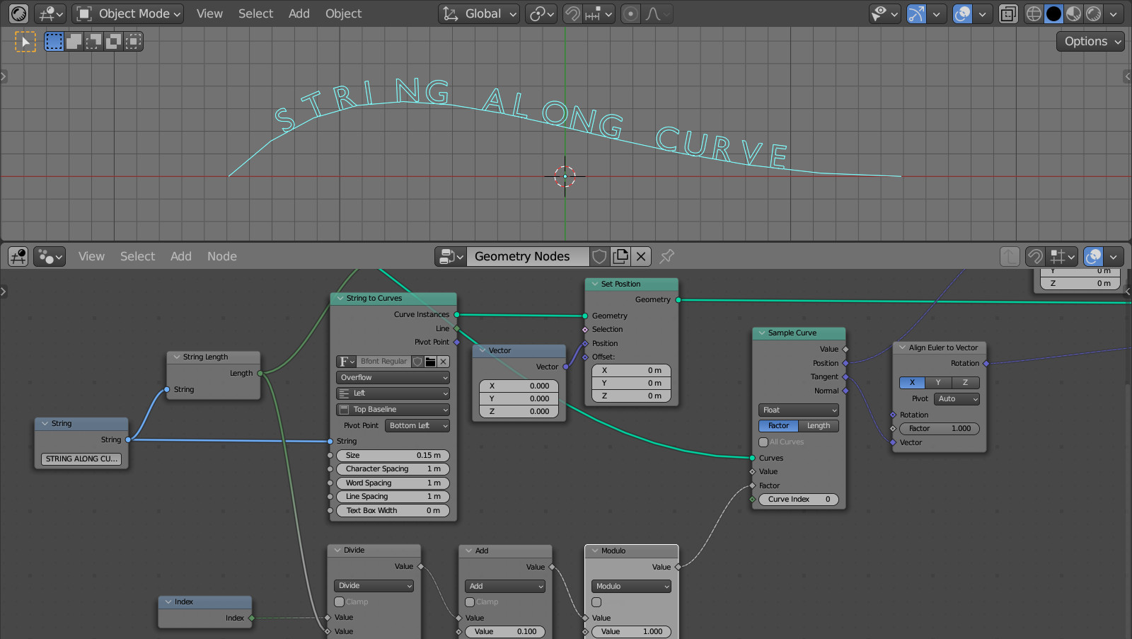
By changing the value in the free field of the Add node, we can move the text along the curve to the position we want.
I had made a different bezier curve and on my resample curve node I got ‘input geometry has unsupported type: mesh’, to fix it I added a Mesh to Curve between Group Input and Resample Curve.
Maybe you have created not curve, but the mesh curve? In this case, you really need to convert it to curve with nodes.
Thank you! Hopefully soon they will have a single node that’ll make this all obsolete but until then this was a lifesaver!
Yes, single node would be great. But now we have what we have.